| Signal Processing Toolbox | |
Calculate the order and cutoff frequency for a Butterworth filter.
Syntax
[n,Wn]=buttord(Wp,Ws,Rp,Rs) [n,Wn]=buttord(Wp,Ws,Rp,Rs,'s')
Description
buttord calculates the minimum order of a digital or analog Butterworth filter required to meet a set of filter design specifications.
Digital Domain
[n,Wn] = buttord(Wp,Ws,Rp,Rs)
returns the lowest order, n, of the digital Butterworth filter that loses no more than Rp dB in the passband and has at least Rs dB of attenuation in the stopband. The scalar (or vector) of corresponding cutoff frequencies, Wn, is also returned. Use the output arguments n and Wn in butter.
Choose the input arguments to specify the stopband and passband according to the following table.
Use the following guide to specify filters of different types.
If your filter specifications call for a bandpass or bandstop filter with unequal ripple in each of the passbands or stopbands, design separate lowpass and highpass filters according to the specifications in this table, and cascade the two filters together.
Analog Domain
[n,Wn] = buttord(Wp,Ws,Rp,Rs,' finds the minimum order s')
n and cutoff frequencies Wn for an analog Butterworth filter. You specify the frequencies Wp and Ws similar to Table 7-1, Description of Stopband and Passband Filter Parameters, only in this case you specify the frequency in radians per second, and the passband or the stopband can be infinite.
Use buttord for lowpass, highpass, bandpass, and bandstop filters as described in Table 7-2, Filter Type Stopband and Passband Specifications.
Example 1
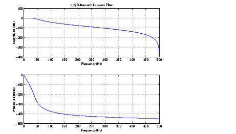
For data sampled at 1000 Hz, design a lowpass filter with less than 3 dB of ripple in the passband, defined from 0 to 40 Hz, and at least 60 dB of attenuation in the stopband, defined from 150 Hz to the Nyquist frequency (500 Hz). Plot the filter's frequency response.
Wp=40/500; Ws=150/500; [n,Wn]=buttord(Wp,Ws,3,60) n = 5 Wn = 0.0810 [b,a]=butter(n,Wn); freqz(b,a,512,1000); title('n=5 Butterworth Lowpass Filter')
Example 2
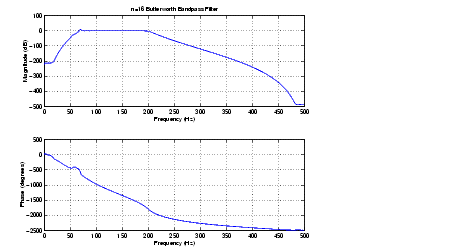
Next design a bandpass filter with passband of 60 Hz to 200 Hz, with less than 3 dB of ripple in the passband, and 40 dB attenuation in the stopbands that are 50 Hz wide on both sides of the passband.
Wp=[60 200]/500; Ws=[50 250]/500; Rp=3; Rs=40; [n,Wn]=buttord(Wp,Ws,Rp,Rs) n = 16 Wn = 0.1198 0.4005 [b,a]=butter(n,Wn); freqz(b,a,128,1000) title('n=16 Butterworth Bandpass Filter')
Algorithm
buttord's order prediction formula is described in [1]. It operates in the analog domain for both analog and digital cases. For the digital case, it converts the frequency parameters to the s-domain before estimating the order and natural frequency, and then converts back to the z-domain.
buttord initially develops a lowpass filter prototype by transforming the passband frequencies of the desired filter to 1 rad/s (for lowpass and highpass filters) and to -1 and 1 rad/s (for bandpass and bandstop filters). It then computes the minimum order required for a lowpass filter to meet the stopband specification.
See Also
|
Design a Butterworth analog or digital filter. |
|
Calculate the order for a Chebyshev type I filter. |
|
Calculate the order for a Chebyshev type II filter. |
|
Calculate the order for an elliptic filter. |
|
Estimate Kaiser window FIR filter parameters. |
References
[1] Rabiner, L.R., and B. Gold. Theory and Application of Digital Signal Processing. Englewood Cliffs, NJ: Prentice-Hall, 1975. Pg. 227.
| | butter | cceps | |
 radians per sample.