
| Power System Blockset |   |
Implement a two- or three- winding saturable transformer.
Library
Description
The Saturable Transformer block model shown below consists of three coupled windings wound on the same core.

The model takes into account the winding resistances (R1 R2 R3), the leakage inductances (L1 L2 L3) as well as the magnetizing characteristics of the core which is modeled by a resistance Rm simulating the core active losses and a saturable inductance Lsat. The saturation characteristic is specified as a picewise linear characteristic.
The Per Unit Conversion
In order to comply with the industry practice, you must specify the resistance and inductance of the windings in per unit (p.u.). the values are based on the transformer rated power Pn in VA, nominal frequency fn in Hz, and nominal voltage Vn, in Vrms, of the corresponding winding. For each winding the per unit resistance and inductance are defined as:

The base resistance and base inductance used for each winding are:

For the magnetization resistance Rm, the p.u. values are base on the transformer rated power and on nominal voltage of the winding one.
The default parameters of winding one specified in the dialog box section give the following bases:

Suppose that the winding 1 parameters are R1=1.44  and L1=0.1528 H, the corresponding values to be entered in the dialog box are:

Saturation Characteristic
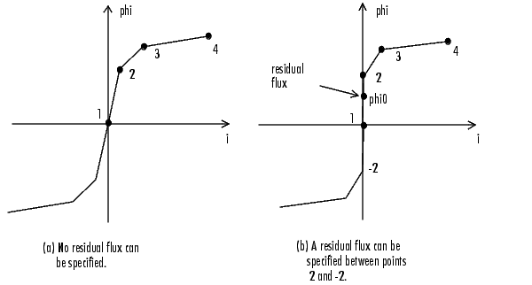
The saturation characteristic of the Saturable Transformer block is defined by a piece-wise linear relationship between the flux and the magnetization current.

Therefore, if you want to specify a residual flux phi0 the second point of the saturation characteristic should correspond to a zero current as shown on the figure (b).
The saturation characteristic is entered as (i, phi) pair values in per unit, starting with pair (0,0). The Power System Blockset converts the vector of fluxes  pu and the vector of currents Ipu into standard units to be used in saturation model of the Saturable Transformer block

where the base flux ( base) and base current (Ibase) are the in peak values obtained at nominal voltage power and frequency:

Dialog Box and Parameters
0 implements a Saturable Transformer block with only two windings and a new icon will be displayed: 
Inputs and Outputs
Input one, output one and output three (if it exists) are at the same instantaneous polarity.
If you set the entry for the third winding to zero, the blockset will consider a transformer with two windings and a new icon will be displayed:

Limitations
Windings can be left floating (i.e not connected by an impedance to the rest of the circuit). However the floating winding will be connected internally to the main circuit through a resistor. This invisible connection does not affect voltage and current measurements.
The flux saturation model does not include hysteresis.
Example
Energization of one phase of a three-phase 450 MVA, 500/230 kV transformer on a 3000 MVA source. The transformer parameters are:
Nominal power: 150e6, 60Hz, Winding 1 parameters (primary): 500e3Vrms/sqrt(3), R=0.002p.u. X=0.08p.u., winding 2 parameters (secondary): 230e3Vrms/sqrt(3), R=0.002p.u. X=0.08p.u., Core loss resistance: 1000p.u., Saturation characteristic: [0 0; 0 1.2; 1.0 1.52], residual flux=0.8p.u.
This circuit is available in the psbxfosaturable.mdl file.
As the source is resonant at the 4th harmonic, you can observe a high fourth harmonic content in the secondary voltage. In this circuit the flux is calculated in two ways:
Simulation of this circuit illustrates the saturation effect on the transformer current and voltage:
See Also
Linear Transformer, Mutual Inductance
 | Powergui | Series RLC Branch |  |