
| Power System Blockset |   |
Implement a two winding or three winding linear transformer.
Library
Description
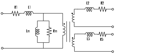
The Linear Transformer block model shown below consists of three coupled windings wound on the same core.

The model takes into account the winding resistances (R1 R2 R3) the leakage inductances (L1 L2 L3) as well as the magnetizing characteristics of the core which is modeled by a linear (Rm Lm) branch.
The Per Unit Conversion
In order to comply with the industry practice, you must specify the resistance and inductance of the windings in per unit (pu). The values are based on the transformer rated power Pn, in VA, nominal frequency fn in Hz, and nominal voltage Vn, in Vrms, of the corresponding winding. For each winding the per unit resistance and inductance are defined as:

The base resistance and base inductance used for each winding are:

For the magnetization resistance Rm and inductance Lm, the p.u. values are based on the transformer rated power and on nominal voltage of the winding one.
For example, the default parameters of winding one specified in the dialog box section give the following bases:

Suppose that the winding 1 parameters are R1=1.44  and L1=0.1528 H, the corresponding values to be entered in the dialog box are:

To specify a magnetizing current of 0.2% (resistive and inductive) based on nominal current you must enter per unit values of 1/0.002 = 500 p.u. for the resistance and the inductance of the magnetizing branch. Using the base values calculated above these per unit values correspond to Rm = 8.6e5 ohms and Lm = 995 henries.
Dialog Box and Parameters
0 implements a Linear Transformer block with two windings and a new icon will be displayed:| Note To implement an ideal transformer model, set the winding resistances and inductances to zero, and the magnetization resistance and inductance to inf. |
Inputs and Outputs
The winding 1 is connected between input one and input two of the Linear Transformer block. The winding 2 is connected between output one and output two, and the winding 3 (if defined) is connected between output three and output four.
Input one, output one and output three (if exist) are at the same instantaneous polarity.
Limitations
Windings can be left floating (i.e., not connected to the rest of the circuit). However the floating winding will be connected internally to the main circuit through a resistor. This internal connection does not affect voltage and current measurements.
Example
Typical residential distribution transformer network feeding line to neutral and line to line loads. This circuit is available in the psbtransformer.mdl file.
See Also
Saturable Transformer, Mutual Inductance
 | Impedance Measurement | MOSFET |  |