
| Stateflow |   |
What Is a Connective Junction?
A connective junction is used to represent a decision point in the Stateflow diagram. The connective junction enables representation of different transition paths. Connective junctions are used to help represent:
if-then-else decision construct by specifying conditions on some or all of the outgoing transitions from the connective junction.for loop construct by having a self loop transition from the connective junction back to itself.See Connective Junctions for a summary of the semantics of connective junctions.
What Is Flow Diagram Notation?
Flow diagram notation is essentially logic represented without the use of states. In some cases, using flow diagram notation is a closer representation of the system's logic and avoids the use of unnecessary states. Flow diagram notation is an effective way to represent common code structures like for loops and if-then-else constructs. The use of flow diagram notation in a Stateflow diagram can produce more efficient code optimized for memory use. Reducing the number of states optimizes memory use.
Flow diagram notation is represented through combinations of self-loops to connective junctions, transitions to and from connective junctions, and inner transitions to connective junctions. The key to representing flow diagram notation is in the labeling of the transitions (specifically the use of action language).
Flow diagram notation and state-to-state transition notation seamlessly coexist in the same Stateflow diagram.
Example: Connective Junction with All Conditions Specified
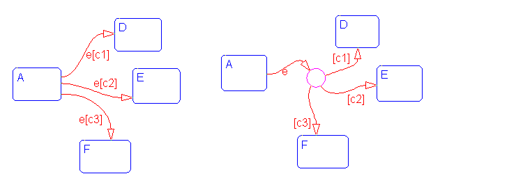
When event e occurs, state A transfers to D, E, or F depending on which of the conditions [c1], [c2], or [c3] is met. With the alternative representation, using a connective junction, the transition from A to the connective junction occurs first, provided the event has occurred. A destination state is then determined based on which of the conditions [c1], [c2], or [c3] is satisfied. The transition from the source state to the connective junction is labeled by the event, and those from the connective junction to the destination states by the conditions. No event is applicable in a transition from a connective junction to a destination state.

See Example: If-Then-Else Decision Construct for information on the semantics of this notation.
Example: Connective Junction with One Unconditional Transition
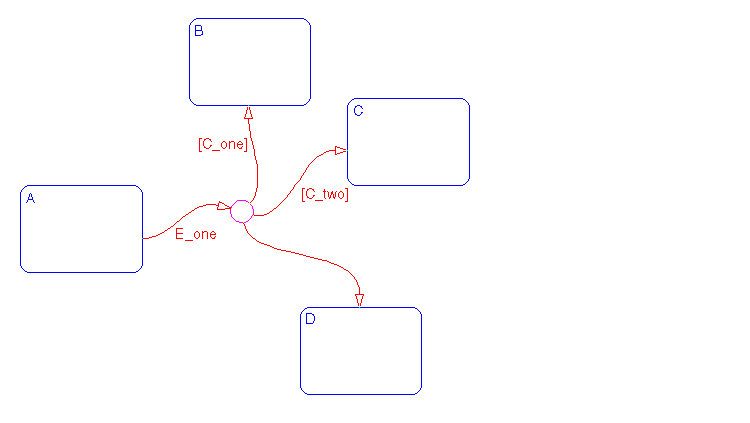
The transition A
B is valid when A is active, event E_one occurs, and [C_one] is true. The transition A
C is valid when A is active, event E_one occurs, and [C_two] is true. Otherwise, given A is active and event E_one occurs, the transition A
D is valid. If you do not explicitly specify condition [C_three], it is implicit that the transition condition is not [C_one] and not [C_two].

See Example: If-Then-Else Decision Construct for information on the semantics of this notation.
Example: Connective Junction Special Case - Self Loop
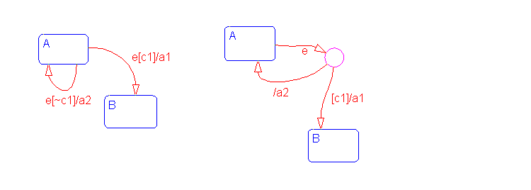
In some situations, the transition event occurs, but the condition is not met. The transition cannot be taken, but an action is generated. You can represent this situation by using a connective junction or a self loop (transition from state to itself).
In state A, event e occurs. If condition [c1] is met, transition A
B is taken, generating action a1. The transition A
A is valid if event e occurs and [c1] is not true. In this self loop, the system exits and re-enters state A, and executes action a2. An alternative representation using a connective junction is shown. The two representations are equivalent; in the one that uses a connective junction, it is not necessary to specify condition [~c1]explicitly, as it is implied.

See Example: Self Loop for information on the semantics of this notation.
Example: Connective Junction and For Loops
This example shows a combination of flow diagram notation and state transition notation. Self loops to connective junctions can be used to represent for loop constructs.
In state A, event E occurs. The transition from state A to state B is valid if the conditions along the transition path are true. The first segment of the transition does not have a condition, but does have a condition action. The condition action, {i=0}, is executed. The condition on the self loop is evaluated as true and the condition actions {i++;func1()} execute. The condition actions execute until the condition, [i<10], is false. The condition actions on both the first segment and the self loop to the connective junction effectively execute a for loop (for i values 0 to 9 execute func1()). The for loop is executed outside of the context of a state. The remainder of the path is evaluated. Since there are no conditions, the transition completes at the destination, state B.

See Example: For Loop Construct for information on the semantics of this notation.
Example: Flow Diagram Notation
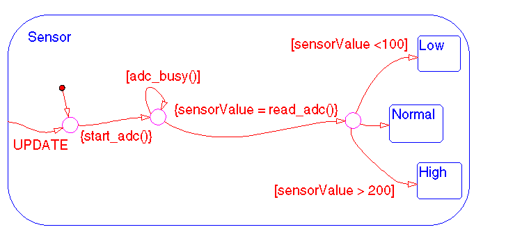
This example shows a real-world use of flow diagram notation and state transition notation. This Stateflow diagram models an 8-bit analog-to-digital converter (ADC).
Consider the case when state Sensor.Low is active and event UPDATE occurs. The inner transition from Sensor to the connective junction is valid. The next transition segment has a condition action, {start_adc()}, which initiates a reading from the ADC. The self-loop on the second connective junction repeatedly tests the condition [adc_busy()]. This condition evaluates as true once the reading settles (stabilizes) and the loop completes. This self loop is used to introduce the delay needed for the ADC reading to settle. The delay could have been represented by using another state with some sort of counter. Using flow notation in this example avoids an unnecessary use of a state and produces more efficient code.
The next transition segment condition action, {sensorValue=read_adc()}, puts the new value read from the ADC in the data object sensorValue. The final transition segment is determined by the value of sensorValue. If [sensorValue <100] is true, the state Sensor.Low is the destination. If [sensorValue >200] is true, the state Sensor.High is the destination. Otherwise, state Sensor.Normal is the destination state.

See Example: Flow Diagram Notation for information on the semantics of this notation.
Example: Connective Junction from a Common Source to Multiple Destinations
Transitions A
B and A
C share a common source state A. An alternative representation uses one arrow from A to a connective junction, and multiple arrows labeled by events from the junction to the destination states B and C.

See Example: Transitions from a Common Source to Multiple Destinations for information on the semantics of this notation.
Example: Connective Junction Common Events
Suppose, for example, that when event e1 occurs, the system, whether it is in state A or B, will transfer to state C. Suppose that transitions A
C and B
C are triggered by the same event e1, so that both destination state and trigger event are common between the transitions. There are three ways to represent this:
A and B to C, each labeled with e1A and B in one superstate S, and drawing one transition from S to C, labeled with e1A and B to a connective junction, then drawing one transition from the junction to C, labeled with e1This Stateflow diagram shows the simplification using a connective junction.

See Example: Transitions from a Source to a Destination Based on a Common Event for information on the semantics of this notation.
 | What Is a Self Loop Transition? | History Junctions |  |