

| Stateflow |   |
Example: If-Then-Else Decision Construct
This example shows the semantics of an if-then-else decision construct.
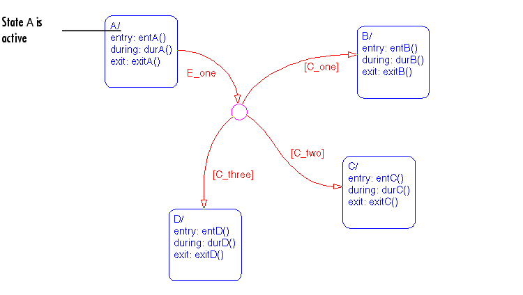
Initially the Stateflow diagram is asleep. State A is active. Event E_one occurs and awakens the Stateflow diagram. Condition [C_two] is true. Event E_one is processed from the root of the Stateflow diagram down through the hierarchy of the Stateflow diagram:
E_one. There is a valid transition segment from state A to the connective junction. The transition segments beginning from a twelve o'clock position on the connective junction are evaluated for validity. The first transition segment labeled with condition [C_one] is not valid. The next transition segment labeled with the condition [C_two] is valid. The complete transition from state A to state C is valid.
A executes and completes exit actions (exitA()).
A is marked inactive.
C is marked active.
C executes and completes entry actions (entC()).
This sequence completes the execution of this Stateflow diagram associated with event E_one.
Example: Self Loop
This example shows the semantics of a self loop using a connective junction.
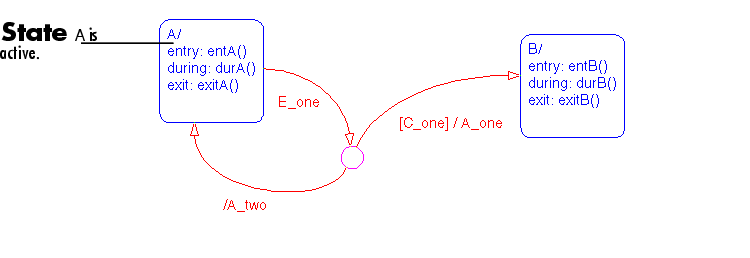
Initially the Stateflow diagram is asleep. State A is active. Event E_one occurs and awakens the Stateflow diagram. Condition [C_one] is false. Event E_one is processed from the root of the Stateflow diagram down through the hierarchy of the Stateflow diagram:
E_one. There is a valid transition segment from state A to the connective junction. The transition segment labeled with a condition and action is evaluated for validity. Since the condition [C_one] is not valid, the complete transition from state A to state B is not valid. The transition segment from the connective junction back to state A is valid.
A executes and completes exit actions (exitA()).
A is marked inactive.
A_two is executed and completed.
A is marked active.
A executes and completes entry actions (entA()).
This sequence completes the execution of this Stateflow diagram associated with event E_one.
Example: For Loop Construct
This example shows the semantics of a for loop.
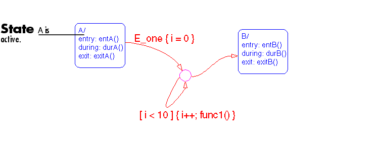
Initially the Stateflow diagram is asleep. State A is active. Event E_one occurs and awakens the Stateflow diagram. Event E_one is processed from the root of the Stateflow diagram down through the hierarchy of the Stateflow diagram.
E_one. There is a valid transition segment from state A to the connective junction. The transition segment condition action, i = 0, is executed and completed. Of the two transition segments leaving the connective junction, the transition segment that is a self loop back to the connective junction is evaluated next for validity. That segment takes priority in evaluation because it has a condition specified whereas the other segment is unlabeled.
i < 10 ] is evaluated as true. The condition actions, i++, and a call to func1 are executed and completed until the condition becomes false. A connective junction is not a final destination; thus the transition destination remains to be determined.
B is now valid. The complete transition from state A to state B is valid.
A executes and completes exit actions (exitA()).
A is marked inactive.
B is marked active.
B executes and completes entry actions (entB()).
This sequence completes the execution of this Stateflow diagram associated with event E_one.
Example: Flow Diagram Notation
This example shows the semantics of a Stateflow diagram that uses flow notation.
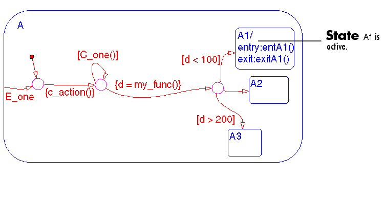
Initially the Stateflow diagram is asleep. State A.A1 is active. The condition [C_one()] is initially true. Event E_one occurs and awakens the Stateflow diagram. Event E_one is processed from the root of the Stateflow diagram down through the hierarchy of the Stateflow diagram:
E_one. There is no valid transition.
A checks itself for valid transitions and detects a valid inner transition to a connective junction.
[C_one()] is tested and is true; the self loop is taken. Since a final transition destination has not been reached, this self loop continues until [C_one()] is false. Assume that after five loops [C_one()] is false.
{d=my_func()}, is executed and completed. The returned value of d is 84.
[d<100] is evaluated first based on the geometry of the two outgoing conditional transition segments. Since the return value of d is 84, the condition [d<100] is true and this transition (to the destination state A.A1) is valid.
A.A1 exit actions execute and complete (exitA1()).
A.A1 is marked inactive.
A.A1 is marked active.
A.A1 entry actions execute and complete (entA1()).
This sequence completes the execution of this Stateflow diagram associated with event E_one.
Example: Transitions from a Common Source to Multiple Destinations
This example shows the semantics of transitions from a common source to multiple destinations.
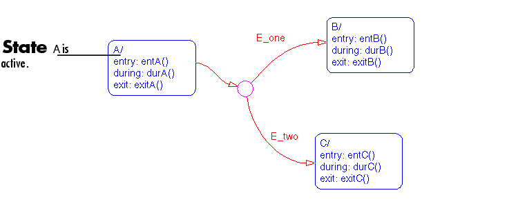
Initially the Stateflow diagram is asleep. State A is active. Event E_two occurs and awakens the Stateflow diagram. Event E_two is processed from the root of the Stateflow diagram down through the hierarchy of the Stateflow diagram:
E_two. There is a valid transition segment from state A to the connective junction. Given that the transition segments are equivalently labeled, evaluation begins from a twelve o'clock position on the connective junction and progresses clockwise. The first transition segment labeled with event E_one is not valid. The next transition segment labeled with event E_two is valid. The complete transition from state A to state C is valid.
A executes and completes exit actions (exitA()).
A is marked inactive.
C is marked active.
C executes and completes entry actions (entC()).
This sequence completes the execution of this Stateflow diagram associated with event E_two.
Example: Transitions from Multiple Sources to a Common Destination
This example shows the semantics of transitions from multiple sources to a single destination.
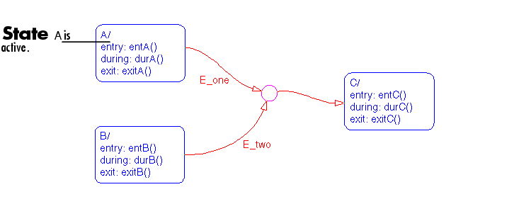
Initially the Stateflow diagram is asleep. State A is active. Event E_one occurs and awakens the Stateflow diagram. Event E_one is processed from the root of the Stateflow diagram down through the hierarchy of the Stateflow diagram.
E_one. There is a valid transition segment from state A to the connective junction and from the junction to state C.
A executes and completes exit actions (exitA()).
A is marked inactive.
C is marked active.
C executes and completes entry actions (entC()).
This sequence completes the execution of this Stateflow diagram associated with event E_one.
Example: Transitions from a Source to a Destination Based on a Common Event
This example shows the semantics of transitions from multiple sources to a single destination based on the same event.
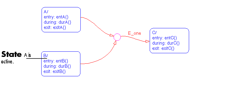
Initially the Stateflow diagram is asleep. State B is active. Event E_one occurs and awakens the Stateflow diagram. Event E_one is processed from the root of the Stateflow diagram down through the hierarchy of the Stateflow diagram:
E_one. There is a valid transition segment from state B to the connective junction and from the junction to state C.
B executes and completes exit actions (exitB()).
B is marked inactive.
C is marked active.
C executes and completes entry actions (entC()).
This sequence completes the execution of this Stateflow diagram associated with event E_one.
 | Inner Transitions | Event Actions |  |