
| Stateflow |   |
Example Stateflow Diagram
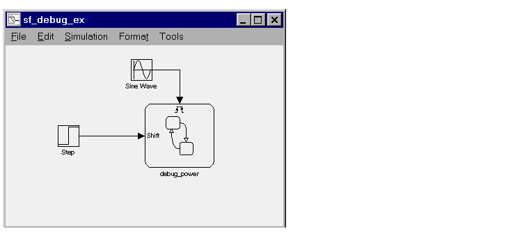
This example Simulink model and Stateflow diagram is used to show how to debug some typical runtime errors.


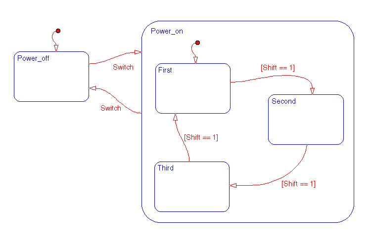
The Stateflow diagram has two states at the highest level in the hierarchy, Power_off and Power_on. By default Power_off is active. The event Switch toggles the system between being in Power_off and Power_on. Switch is defined as an Input from Simulink event. Power_on has three substates, First, Second, and Third. By default, when Power_on becomes active, First also becomes active. Shift is defined as an Input from Simulink data object. When Shift equals 1, the system transitions from First to Second, Second to Third, Third to First, and then the pattern repeats.
In the Simulink model, there is an event input and a data input. A Sine wave block is used to generate a repeating input event that corresponds with the Stateflow event Switch. The Step block is used to generate a repeating pattern of 1 and 0 that corresponds with the Stateflow data object Shift. Ideally, the Switch event occurs in a frequency that allows at least one cycle through First, Second, and Third.
 | Stateflow Debugger User Interface | Typical Scenario to Debug Runtime Errors |  |