

| Stateflow |   |
Stateflow Diagram Objects
This sample Stateflow diagram highlights some key graphical components. The sections that follow describe these graphical components as well as some nongraphical objects and related concepts in greater detail.
Figure 2-1: Graphical Components
States
A state describes a mode of an event-driven system. The activity or inactivity of the states dynamically changes based on events and conditions.
Every state has a parent. In a Stateflow diagram consisting of a single state, that state's parent is the Stateflow diagram itself (also called the Stateflow diagram root). You can place states within other higher-level states. In the figure, StateA1 is a child in the hierarchy to StateA.
A state also has history. History provides an efficient means of basing future activity on past activity.
States have labels that can specify actions executed in a sequence based upon action type. The action types are entry, during, exit, and on.
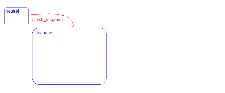
In an automatic transmission example, the transmission can either be in neutral or engaged in a gear. Two states of the transmission system are neutral and engaged.

Stateflow provides two types of states: parallel (AND) and exclusive (OR) states. You represent parallelism with AND (parallel) states. The transmission example shows exclusive (OR) states. Exclusive (OR) states are used to describe modes that are mutually exclusive. The system is either in the neutral state or the engaged state at any one time.
Transitions
A transition is a graphical object that, in most cases, links one object to another. One end of a transition is attached to a source object and the other end to a destination object. The source is where the transition begins and the destination is where the transition ends. A transition label describes the circumstances under which the system moves from one state to another. It is always the occurrence of some event that causes a transition to take place. In the figure, the transition from StateA1 to StateA2 is labeled with the event transitionA1_A2 that triggers the transition to occur.
Consider again the automatic transmission system. clutch_engaged is the event required to trigger the transition from neutral to engaged.
Events
Events drive the Stateflow diagram execution. Events are nongraphical objects and are thus not represented directly in the figure. All events that affect the Stateflow diagram must be defined. The occurrence of an event causes the status of the states in the Stateflow diagram to be evaluated. The broadcast of an event can trigger a transition to occur or can trigger an action to be executed. Events are broadcast in a top-down manner starting from the event's parent in the hierarchy.
Events are created and modified using the Stateflow Explorer. Events can be created at any level in the hierarchy. Events have properties such as a scope. The scope defines whether the event is:
Data
Data objects are used to store numerical values for reference in the Stateflow diagram. Data objects are nongraphical objects and are thus not represented directly in the figure.
Data objects are created and modified using the Stateflow Explorer. Data objects can be created at any level in the hierarchy. Data objects have properties such as a scope. The scope defines whether the data object is:
Hierarchy
Hierarchy enables you to organize complex systems by defining a parent and offspring object structure. A hierarchical design usually reduces the number of transitions and produces neat, manageable diagrams. Stateflow supports a hierarchical organization of both charts and states. Charts can exist within charts. A chart that exists in another chart is known as a subchart.
Similarly, states can exist within other states. Stateflow represents state hierarchy with superstates and substates. For example, this Stateflow diagram has a superstate that contains two substates.
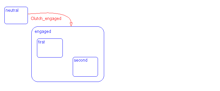
The engaged superstate contains the first and second substates. The engaged superstate is the parent in the hierarchy to the states first and second. When the event clutch_engaged occurs, the system transitions out of the neutral state to the engaged superstate. Transitions within the engaged superstate are intentionally omitted from this example for simplicity.
A transition out of a higher level, or superstate, also implies transitions out of any active substates of the superstate. Transitions can cross superstate boundaries to specify a substate destination. If a substate is active its parent superstate is also active.
Conditions
A condition is a Boolean expression specifying that a transition occurs, given that the specified expression is true. In the component summary Stateflow diagram, [condition1] represents a Boolean expression that must be true for the transition to occur.
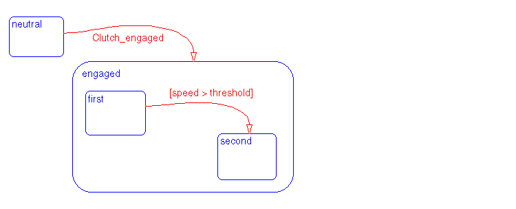
In the automatic transmission system, the transition from first to second occurs if the Boolean condition [speed > threshold] is true.
History Junction
History provides the means to specify the destination substate of a transition based on historical information. If a superstate with exclusive (OR) decomposition has a history junction, the transition to the destination substate is defined to be the substate that was most recently visited. A history junction applies to the level of the hierarchy in which it appears. The history junction overrides any default transitions. In the component summary Stateflow diagram, the history junction in StateA1 indicates that when a transition to StateA1 occurs, the substate that becomes active (StateA1a, StateA1b, or StateA1c) is based on which of those substates was most recently active.
In the automatic transmission system, history indicates that when clutch_engaged causes a transition from neutral to the engaged superstate, the substate that becomes active, either first or second, is based on which of those substates was most recently active.
Actions
Actions take place as part of Stateflow diagram execution. The action can be executed either as part of a transition from one state to another or based on the activity status of a state. In the figure, the transition segment from StateA1b to the connective junction is labeled with a condition action (func1()) and a transition action (func2()). The semantics of how and why actions take place are discussed throughout the examples in Chapter 8, Semantics.
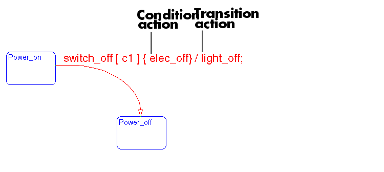
Transitions can have condition actions and transition actions, as shown in this example.
States can have entry, during, exit, and on event_name actions. For example,
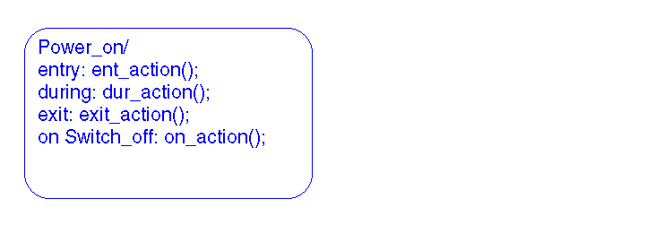
The action language defines the types of actions you can specify and their associated notations. An action can be a function call, an event to be broadcast, a variable to be assigned a value, etc.
Stateflow supports both Mealy and Moore finite state machine modeling paradigms. In the Mealy model, actions are associated with transitions, whereas in the Moore model they are associated with states. Stateflow supports state actions, transition actions, and condition actions. For more information, see the section titled What Is an Action Language?.
Parallelism
A system with parallelism has two or more states that can be active at the same time. The activity of each parallel state is essentially independent of other states. In the figure, StateA2a and StateA2b are parallel (AND) states. StateA2 has parallel (AND) state decomposition.
For example, this Stateflow diagram has parallel superstate decomposition.
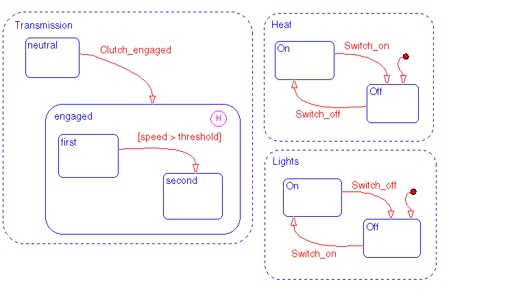
The transmission, heating, and light systems are parallel subsystems in a car. They exist in parallel and are physically independent of each other. There are many other parallel components in a car, such as the braking and windshield wiper subsystems.
You represent parallelism in Stateflow by specifying parallel (AND) state decomposition. Parallel (AND) states are displayed as dashed rectangles.
Default Transitions
Default transitions specify which exclusive (OR) state is to be active when there is ambiguity between two or more exclusive (OR) states at the same level in the hierarchy. In the figure, when StateA is active, by default StateA1 is also active. Without the default transition to StateA1, there is ambiguity in whether StateA1 or StateA2 should be active.
In the Lights subsystem, the default transition to the Lights.Off substate indicates that when the Lights superstate becomes active, the Off substate becomes active by default.

Default transitions specify which exclusive (OR) substate in a superstate the system enters by default, in the absence of any information. History junctions override default transition paths in superstates with exclusive (OR) decomposition.
Connective Junctions
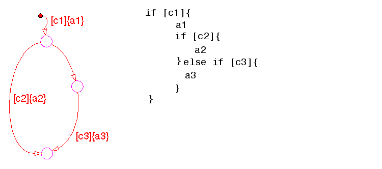
Connective junctions are decision points in the system. A connective junction is a graphical object that simplifies Stateflow diagram representations and facilitates generation of efficient code. Connective junctions provide alternative ways to represent desired system behavior. In the figure, the connective junction is used as a decision point for two transition segments that complete at StateA1c.
This example shows how connective junctions (displayed as small circles) are used to represent the flow of an if code structure.
 | Defining Stateflow Interfaces | Exploring a Real-World Stateflow Application |  |