

| Real-Time Workshop User's Guide |   |
Real-Time Workshop generates optimized, portable, and customizable code from Simulink models. Using integrated makefile based targeting support, it builds programs that can help speed up your simulations, provide intellectual property protection, or run on a wide variety of real-time rapid prototyping or production targets. Simulink's external mode run-time monitor works seamlessly with real-time targets, providing an elegant signal monitoring and parameter tuning interface. Real-Time Workshop supports continuous-time, discrete-time and hybrid systems, including conditionally executed and atomic systems. Real-Time Workshop accelerates your development cycle, producing higher quality results in less time.
Real-Time Workshop is a key link in the set of system design tools provided by The MathWorks. Conceptually, Real-Time Workshop is the final piece in the design process.
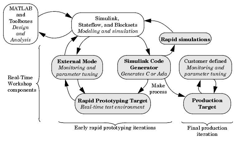
Real-Time Workshop provides a real-time development environment -- a direct path from system design to hardware implementation. You can shorten development cycles and reduce costs with Real-Time Workshop by testing design iterations with real-time hardware. Real-Time Workshop supports the execution of dynamic system models on hardware by automatically converting models to code and providing model-based debugging support. It is well suited for accelerating simulations, rapid prototyping, turnkey solutions, and production embedded real-time applications.
With Real-Time Workshop, you can quickly generate C code for discrete-time, continuous-time, and hybrid systems, including systems containing triggered and enabled subsystems. With the optional Real-Time Workshop Ada Coder, you can generate Ada code. The optional Stateflow Coder add-on lets you generate code for finite state machines modeled in Stateflow.
System design using the MathWorks toolset differs from one application to another. A typical product cycle starts with modeling in Simulink, followed by an analysis of the simulations in MATLAB. During the simulation process, you use the rapid simulation features of Real-Time Workshop to speed up your simulations.
After you are satisfied with the simulation results, you use Real-Time Workshop in conjunction with a rapid prototyping target, such as xPC Target. The rapid prototyping target is connected to your physical system. You test and observe your system, using your Simulink model as the interface to your physical target. After creating your model, you use Real-Time Workshop to transform your model to C or Ada code. An extensible make process and download procedure creates an executable for your model and places it on the target system. Finally, using external mode, you can monitor and tune parameters in real-time as your model executes on the target environment.
Conceptually, there are two types of targets: rapid prototyping targets and the embedded target. Code generated for the rapid prototyping targets supports increased monitoring and tuning capabilities. The generated embedded code used in the embedded target is highly optimized and suitable for deployment in production systems. You can add application-specific entry points to monitor signals and tune parameters in the embedded code.
The basic components of Real-Time Workshop are:
Integrated Development Environment
If the Real-Time Workshop target you are using supports Simulink external mode, you can use Simulink as the monitoring/debugging interface for the generated code. With external mode, you can:
set_param MATLAB command. The set_param command lets you interact programmatically with your target.These concepts are illustrated by Figure 1-1 and Figure 1-2.
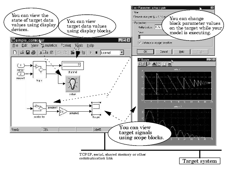
Figure 1-1: Signal Viewing and Parameter Tuning in External Mode
Figure 1-2: Dials and Gauges Provide Front End to Target System
A Next-Generation Development Tool
The MathWorks toolset, including Simulink and Real-Time Workshop, is revolutionizing the way embedded systems are designed. Simulink is a very high level language (VHLL) -- a next-generation programing language. A brief look at the history of dynamic and embedded system design methodologies reveals a steady progression toward higher-level design tools and processes:
The Simulink code generator included within Real-Time Workshop is a next-generation graphical block diagram compiler. Real-Time Workshop has capabilities beyond those of a typical HLL compiler. Generated code is highly readable and customizable. It is normally unnecessary to read the object code produced by the HLL compiler.. You can use the Real-Time Workshop in a wide variety of applications, improving your design process.
Key Features
The general goal of the MathWorks toolset, including Real-Time Workshop, is to enable you to accelerate your design process while reducing cost, decreasing time to market, and improving quality.
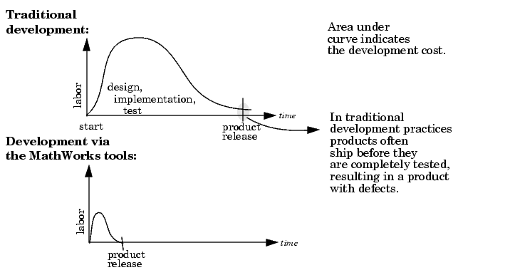
Traditional development practices tend to be very labor intensive. Poor tools often lead to a proliferation of ad hoc software projects that fail to deliver reusable code. With the MathWorks toolset, you can focus energy on design and achieve better results in less time with fewer people.
Real-Time Workshop, along with other components of the MathWorks tools, provides:
The following features of Real-Time Workshop enable you to reach the above goal:
char, short, int, and long in embedded C compiler environments (usually 8, 16, and 32 bits).hilite_system recognizes these tags and highlights the corresponding blocks in your model.Benefits
You can benefit by using Real-Time Workshop in the following applications. This is not an exhaustive list, but a general survey.
Real-Time Workshop lets you generate, cross-compile, link, and download production quality C or Ada code for real-time systems (such as controllers or DSP applications) onto your target processor directly from Simulink. You can customize the generated code by inserting S-functions into your model and specifying, via the Target Language Compiler, what the generated code should look like. Using the optimized, automatically generated code, you can focus your coding efforts on specific features of your product, such as device drivers and general device interfacing.
As a rapid prototyping tool, Real-Time Workshop enables you to implement your embedded systems designs quickly, without lengthy hand-coding and debugging. Rapid prototyping is typically used in the software/hardware integration and testing phases of the design cycle enabling you to:
You can use Real-Time Workshop to generate downloadable, targeted C code that runs on top of a real-time operating system (RTOS). Alternatively, you can generate code to run on the bare hardware at interrupt level, using a simple rate monotonic scheduling executive that you create from examples provided with the Real-Time Workshop. There are many rapid prototyping targets provided; or you can create your own.
During rapid prototyping, the generated code is fully instrumented enabling direct access via Simulink external mode for easy monitoring and debugging. The generated code contains a data structure that encapsulates the details of your model. This data structure is used in the bidirectional connection to Simulink running in external mode. Using Simulink external mode, you can monitor signal and tune parameters to further refine your model in rapid iterations enabling you to achieve desired results quickly.
You can create and execute code for an entire system or specified subsystems for hardware-in-the-loop simulations. Typical applications include training simulators, real-time model validation, and prototype testing.
Bundled Real-Time Workshop targets and third-party turnkey solutions support a variety of control and DSP applications. The target environments include embedded PC, PCI, ISA, VME, and custom hardware, running off-the-shelf real-time operating systems, DOS, or Microsoft Windows. Target system processor architectures include Motorola MC680x0 and PowerPC processors, Intel-80x86 and compatibles, Alpha, and Texas Instruments DSPs. Third-party vendors are regularly adding other architectures. For a current list of third-party turnkey solutions, see the MATLAB Connections Web page: http://www.mathworks.com/products/connections.
The open environment of Real-Time Workshop also lets you create your own turnkey solution.
The S-Function Target, in addition to speeding up your simulation, allows you to protect your intellectual property: the designs and algorithms embodied in your models. Using the S-Function Target, you can generate and distribute binaries from your models or subsystems. End users have access to the interface, but not to the body, of your algorithms.
The MathWorks tools can be used in the design of most dynamic systems. Generally Simulink is either used to model a high-fidelity dynamic system (e.g., an engine) or a real-time system (such as an engine controller or a signal processing system).
When modeling high-fidelity systems, you can use Real-Time Workshop to accelerate the design process by speeding up your simulations. This is achieved by using one of the following Real-Time Workshop components:
The MathWorks Tools and the Development Process
Figure 1-3 is a high-level view of a traditional development process without the MathWorks toolset.
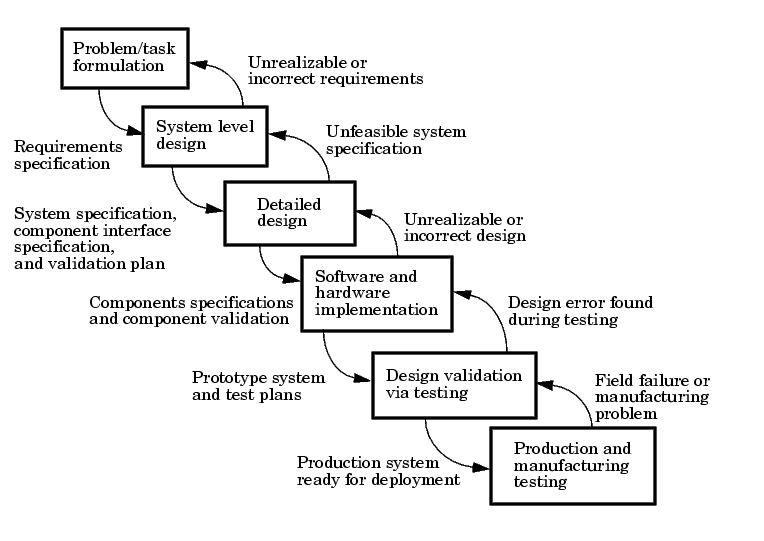
Figure 1-3: Traditional Development Process Without MathWorks Toolset
In Figure 1-3, each block represents a work phase. Documents are used to coordinate the different work phases. In this environment, it is easy to go back one work phase, but hard to go back multiple work phases. In this environment, design engineers (such as control system engineers or signal processing engineers) are not usually involved in the prototyping phase until many months after they have specified the design. This can result in poor time to market and inferior quality.
In this environment, different tools are used in each phase. Designs are communicated via paper. This enforces a serial, rather than an iterative, development process. Developers must re-enter the result of the previous phase before they can begin work on a new phase. This leads to miscommunication and errors, resulting in lost work hours. Errors found in later phases are very expensive and time consuming to correct. Correction often involves going back several phases. This is difficult because of the poor communication between the phases.
The MathWorks does not suggest or impose a development process. The MathWorks toolset can be used to complement any development process. In the above process, use of our tools in each phase can help eliminate paper work.
Our toolset also lends itself well to the spiral design process shown in Figure 1-4.
Figure 1-4: Spiral Design Process
Using the MathWorks toolset, your model represents your understanding of your system. This understanding is passed from phase to phase in the model, reducing the need to go back to a previous phase. In the event that rework is necessary in a previous phase, it is easier to transition back one or more phases, because the same model and tools are used in all phases.
A spiral design process iterates quickly between phases, enabling engineers to work on innovative features. The only way to do this cost effectively is to use tools that make it easy to move from one phase to another. For example, in a matter of minutes a control system engineer or a signal processing engineer can validate an algorithm on a real-world rapid prototyping system. The spiral process lends itself naturally to parallelism in the overall development process. You can provide early working models to validation and production groups, involving them in your system development process from the start. This helps compress the overall development cycle while increasing quality.
Another advantage of the MathWorks toolset is that it enables people to work on tasks that they are good at and enjoy doing. For example, control system engineers specialize in design control laws, while embedded system engineers enjoy pulling together a system consisting of hardware and low-level software. It is possible to have very talented people perform different roles, but it is not efficient. Embedded system engineers, for example, are rewarded by specifying and building the hardware and creating low-level software such as device drivers, or real-time operating systems. They do not find data entry operations, such as the manual conversion of a set of equations to efficient code, to be rewarding. This is where the MathWorks toolset shines. The equations are represented as models and Real-Time Workshop converts them to highly efficient code ready for deployment.
Role of the MathWorks Tools in Your Development Process
The following figure outlines where the MathWorks toolset, including Real-Time Workshop, helps you in your development process.
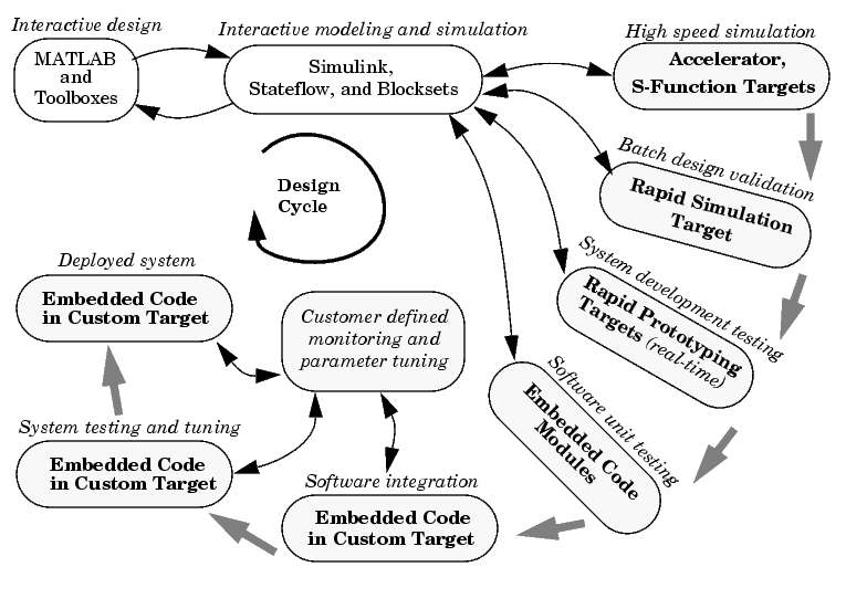
Early in the design phase, you will start with MATLAB and Simulink to help you formulate your problems and create your initial design. Real-Time Workshop helps with this process by enabling high-speed simulations via Simulink Accelerator (also part of Simulink Performance Tools), and the S-function Target for componentization and model speed-up.
After you have a functional model, you may need to tune your model's coefficients. This can be done quickly using Real-Time Workshop's Rapid Simulation Target for Monte-Carlo type simulations (varying coefficients over many simulations).
After you've tuned your model, you can move into system development testing by exercising your model on a rapid prototyping system such as Real-Time Windows Target or xPC Target. With a rapid prototyping target, you connect your model to your physical system. This lets you locate design flaws or modeling errors quickly.
After your prototype system is created, you can use Real-Time Workshop Embedded Coder to create embeddable code for deployment on your custom target. The signal monitoring and parameter tuning capabilities enable you to easily integrate the embedded code into a production environment equipped with debugging and upgrade capabilities.
Code Formats
The Real-Time Workshop code generator transforms your model to HLL code. Real-Time Workshop supports a variety of code formats designed for different execution environments, or targets.
In the traditional embedded system development process, an engineer develops an algorithm (or equations) to be implemented in an embedded system. These algorithms are manually converted to a computer language such as C or Ada. This translation process, usually done by an embedded system engineer, is much like data entry.
Using Simulink to specify the algorithm (or equations), and Real-Time Workshop to generate corresponding code, engineers can bypass this redundant translation step. This enables embedded system engineers to focus on the key issues involved in creating an embedded system: the hardware configuration, device drivers, supervisory logic, and supporting logic for the model equations. Simulink itself is the programming language that expresses the algorithmic portion of the system.
The Simulink code generator provided with Real-Time Workshop is an open "graphical compiler" supporting a variety of code formats. The relationship between code formats and targets is shown below.
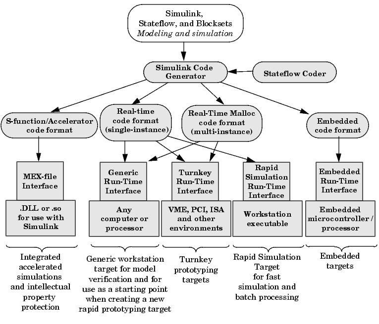
Figure 1-5: Relationship Between Code Formats and Targets
S-Function/Accelerator Code Format
This code format, used by the S-Function Target and Simulink Accelerator, generates code that conforms to Simulink C MEX S-function API.
Real-Time Code Format
The real-time code format is ideally suited for rapid prototyping. This code format (C only) supports increased monitoring and tuning capabilities, enabling easy connection with external mode. Real-time code format supports continuous-time models, discrete-time single- or multirate models, and hybrid continuous-time and discrete-time models. Real-time code format supports both inlined and noninlined S-functions. Memory allocation is declared statically at compile time.
Real-Time Malloc Code Format
The real-time malloc code format is similar to the real-time code format. The primary difference is that the real-time malloc code format declares memory dynamically. This supports multiple instances of the same model, with each instance including a unique data set. Multiple models can be combined into one executable without name clashing. Multiple instances of a given model can also be created in one executable.
Embedded Code Format
The embedded code format is designed for embedded targets. The generated code is optimized for speed, memory usage, and simplicity. Generally, this format is used in deeply embedded or deployed applications. There are no dynamic memory allocation calls; all persistent memory is statically allocated. Real-Time Workshop can generate either C or Ada code in the embedded code format. Note Ada code requires Real-Time Workshop Ada Coder, an add-on product.
The embedded code format provides a simplified calling interface and reduced memory usage. This format manages model and timing data in a compact real-time object structure. This contrasts with the other code formats, which use a significantly larger, model-independent Simulink data structure (SimStruct) to manage the generated code.
The embedded code format improves readability of the generated code, reduces code size, and speeds up execution. The embedded code format supports all discrete-time single- or multirate models.
Because of its optimized and specialized data structures, the embedded code format supports only inlined S-functions.
Target Environments
The Real-Time Workshop supports many target environments. These include ready-to-run configurations and third-party targets. You can also develop your own custom target.
This section begins with a list of available target configurations. Following the list, we summarize the characteristics of each target.
Available Target Configurations
Target Configurations Bundled with Real-Time Workshop. The MathWorks supplies the following target configurations with Real-Time Workshop:
Target Configurations Bundled with Real-Time Workshop Ada Coder. The MathWorks supplies the following target configurations with Real-Time Workshop Ada Coder (a separate product from the Real-Time Workshop):
Target Configurations Bundled with Real-Time Workshop Embedded Coder. The MathWorks supplies the following target configuration with Real-Time Workshop Embedded Coder (a separate product from the Real-Time Workshop):
Turnkey Rapid Prototyping Target Products. These self-contained solutions ( separate products from the Real-Time Workshop) include:
DSP Target Products. See Texas Instruments DSP Developer's Kit User's Guide for information on these targets:
Third-Party Targets. Numerous software vendors have developed customized targets for the Real-Time Workshop. For an up-to-date listing of third-party targets, visit the MATLAB Connections Web page at http://www.mathworks.com/products/connections
View Third-Party Solutions by Product Type, and then select RTW Target.
Custom Targets. Typically, to target custom hardware, you must write a harness (main) program for your target system to execute the generated code, and I/O device drivers to communicate with your hardware. You must also create a system target file and a template makefile.
The Real-Time Workshop supplies generic harness programs as starting points for custom targeting. Chapter 17, Targeting Real-Time Systems provides the information you will need to develop a custom target.
Rapid Simulation Target
Rapid Simulation Target (RSIM) consists of a set of target files for non-real-time execution on your host computer. RSIM enables you to use the Real-Time Workshop to generate fast, stand-alone simulations. RSIM allows batch parameter tuning and downloading of new simulation data (signals) from a standard MATLAB MAT-file without the need to recompile the model.
The speed of the generated code also makes RSIM ideal for Monte Carlo simulations. The RSIM target enables the generated code to read and write data from or to standard MATLAB MAT-files. RSIM reads new signals and parameters from MAT-files at the start of simulation.
RSIM enables you to run stand-alone, fixed-step simulations on your host computer or on additional computers. If you need to run 100 large simulations, you can generate the RSIM model code, compile it, and run the executables on 10 identical computers. The RSIM target allows you to change the model parameters and the signal data, achieving significant speed improvements by using a compiled simulation.
S-Function and Accelerator Targets
S-Function Target provides the ability to transform a model into a Simulink S-function component. Such a component can then be used in a larger model. This allows you to speed up simulations and/or reuse code. You can include multiple instances of the same S-function in the same model, with each instance maintaining independent data structures. You can also share S-function components without exposing the details of the a proprietary source model.
The Accelerator Target is similar to the S-Function Target in that an S-function is created for a model. The Accelerator Target differs from the S-Function Target in that the generated S-function operates in the background. It provides for faster simulations while preserving all existing simulation capabilities (parameter change, signal visualization, full S-function support, etc.).
Turnkey Rapid Prototyping Targets
Real-Time Windows Target and xPC Target are add-on products to Real-Time Workshop. Both of these targets turn an Intel 80x86/Pentium or compatible PC into a real-time system. Both support a large selection of off-the-shelf I/O cards (both ISA and PCI).
With turnkey target systems, all you need to do is install the MathWorks software and a compiler, and insert the I/O cards. You can then use a PC as a real-time system connected to external devices via the I/O cards.
Real-Time Windows Target. Real-Time Windows Target brings rapid prototyping and hardware-in-the-loop simulation to your desktop. It is the most portable solution available today for rapid prototyping and hardware-in-the-loop simulation when used on a laptop outfitted with a PCMCIA I/O card. Real-Time Windows Target is ideal since a second PC or other real-time hardware is often unnecessary, impractical or cumbersome.
This picture shows the basic components of the Real-Time Windows Target.
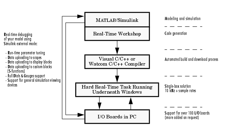
As a prototyping environment, Real-Time Windows Target is exceptionally easy to use, due to tight integration with Simulink and external mode. It is much like using Simulink itself, with the added benefit of gaining real-time performance and connectivity to the real world through a wide selection of supported I/O boards. You can control your real-time execution with buttons located on the Simulink toolbar. Parameter tuning is done "on-the-fly," by simply editing Simulink blocks and changing parameter values. For viewing signals, Real-Time Windows Target uses standard Simulink Scope blocks, without any need to alter your Simulink block diagram. Signal data can also be logged to a file or set of files for later analysis in MATLAB.
Real-Time Windows Target is often called the "one-box rapid prototyping system," since both Simulink and the generated code run on the same PC. A run-time interface enables you to run generated code on the same processor that runs Windows NT or Windows 95/98/2000. The generated code executes in hard real-time, allowing Windows to execute when there are free CPU cycles. Real-Time Windows Target supports over 100 I/O boards, including ISA, PCI, CompactPCI, and PCMCIA. Sample rates in excess of 10 to 20 kHz can be achieved on Pentium PCs.
In universities, Real-Time Windows Target provides a cost effective solution since only a single computer is required. In commercial applications, Real-Time Windows Target is often used at an engineer's desk prior to taking a project to an expensive dedicated real-time testing environment. Its portability is unrivaled, allowing you to use your laptop as a real-time test bed for applications in the field.
Figure 1-6 illustrates the use of Real-Time Windows Target in a model using magnetic levitation to suspend a metal ball in midair. The system is controlled by the model shown in Figure 1-7.
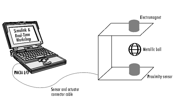
Figure 1-6: Magnetic Levitation System
Figure 1-7: Model for Controlling Magnetic Levitation System
xPC Target. xPC Target is often referred to as a two-box solution. xPC Target requires two PCs: a host PC to run Simulink, and a target PC to run the generated code. The target PC runs an extremely compact real-time kernel that uses 32-bit protected mode. Communication between the host and the target is supported either via an Ethernet networking connection or via a serial cable. Figure 1-8 illustrates the XPC target in a rapid prototyping environment.
Since the target PC is dedicated to running the generated code, xPC Target achieves both increased performance and increased system stability. The target PC is required to have a PC-compatible architecture, but can have any of several form factors, including PC motherboards, CompactPCI,PC104, and single-board computers (SBCs).
xPC Target is also useful in limited production environments. Given the cost of PC hardware, it may make sense to deploy xPC Target in low volume or high-end production systems. This is achieved by using the xPC Target Embedded Option, which is an add-on to xPC Target.
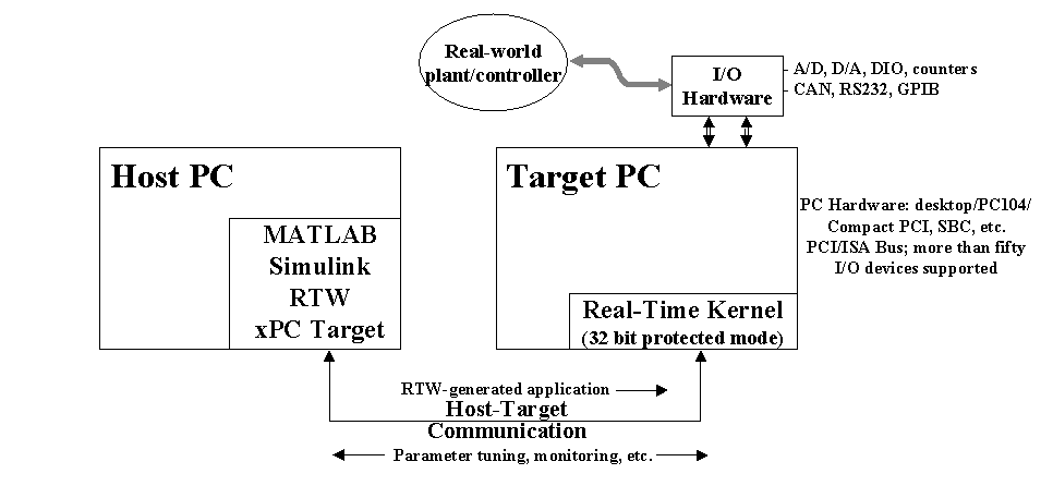
Figure 1-8: xPC Target Rapid Prototyping Environment
Rapid Prototyping Targets
There are two classes of rapid prototyping targets: those using the real-time code format and those using the real-time malloc code format. These differ in the way they allocate memory (statically versus dynamically). Most rapid prototyping targets use the real-time code format.
We define two forms of rapid prototyping environments:
Heterogeneous rapid prototyping environments use rapid prototyping hardware (such as an Intel-80x86/Pentium or similar processor) that differs from the final production hardware. For example, an Intel-80x86/Pentium or similar processor might be used during rapid prototyping of a system that is eventually deployed onto a fixed-point Motorola microcontroller.Homogeneous rapid prototyping environments eliminate uncertainty because the rapid prototyping environment is closer to the final production system. However, a turnkey system for your specific hardware may not exist. In this case, you must weigh the advantages and disadvantages of using one of the existing turnkey systems for heterogeneous rapid prototyping, versus creating a homogeneous rapid prototyping environment.
Several rapid prototyping targets are bundled with Real-Time Workshop.
Generic Real-Time (GRT) Target. This target uses the real-time code format and supports external mode communication. It is designed to be used as a starting point when creating a custom rapid prototyping target, or for validating the generated code on your workstation.
Generic Real-Time Malloc (GRTM) Target. This target is similar to the GRT target but it uses the real-time malloc code format. This format uses the C malloc and free routines to manage all data. With this code format, you can have multiple instances of your model and/or multiple models in one executable.
Tornado Target. The Tornado target uses the real-time or real-time malloc code format. A set of run-time interface files are provided to execute your models on the Wind River System's real-time operating system, VxWorks. The Tornado target supports singletasking, multitasking, and hybrid continuous and discrete-time models.
The Tornado run-time interface and device driver files can also be used as a starting point when targeting other real-time operating system environments. The run-time interface provides full support for external mode, enabling you to take full advantage of the debugging capabilities for parameter tuning and data monitoring via graphical devices.
DOS Target. The DOS target (provided as an example only) uses the real-time code format to turn a PC running the DOS operating system into a real-time system. This target includes a set of run-time interface files for executing the generated code. This run-time interface installs interrupt service routines to execute the generated code and handle other interrupts. While the DOS target is running, the user does not have access to the DOS operating system. Sample device drivers are provided.
The MathWorks recommends that you use Real-Time Windows Target or xPC Target as alternatives to the DOS Target. The DOS target is provided only as an example and its support will be discontinued in the future.
OSEK Targets. The OSEK target (provided as an example only) lets you use the automotive standard open real-time operating system. The run-time interface and OSEK configuration files that are included with this target make it easy to port applications to a wide range of OSEK environments.
Embedded Targets
The embedded real-time target is the main component of the Real-Time Workshop Embedded Coder. It consists of a set of run-time interface files that drive code, generated in the embedded code format, on your workstation. This target is ideal for memory-constrained embedded applications. Real-Time Workshop supports generation of embedded code in both C and Ada.
In its default configuration, the embedded real-time target is designed for use as a starting point for targeting custom embedded applications, and as a means by which you can validate the generated code. To create a custom embedded target, you start with the embedded real-time target run-time interface files and edit them as needed for your application.
In the terminology of Real-Time Workshop, an embedded target is a deeply embedded system. Note that it is possible to use a rapid prototyping target in an embedded (production) environment. This may make more sense in your application.
Code Generation Optimizations
The Simulink code generator included with Real-Time Workshop is packed with optimizations to help create fast and minimal size code. The optimizations are classified either as cross-block optimizations, or block specific optimizations. Cross-block optimizations apply to groups of blocks or the general structure of a model. Block specific optimizations are handled locally by the object generating code for a given block. Listing each block specific optimization here is not practical; suffice it to say that the Target Language Compiler technology generates very tight and fast code for each block in your model.
The following sections discuss some of the cross-block optimizations.
Multirate Support
One of the more powerful features of Simulink is its implicit support for multirate systems. The ability to run different parts of a model at different rates guarantees optimal use of the target processor. In addition, Simulink enforces correctness by requiring that you create your model in a manner that guarantees deterministic execution.
Inlining S-Function Blocks for Optimal Code
The ability to add blocks to Simulink via S-functions is enhanced by the Target Language Compiler. You can create blocks that embed the minimal amount of instructions into the generated code. For example, if you create a device driver using an S-function, you can have the generated code produce one line for the device read, as in the following code fragment.
mdlOutputs(void)
{
    .
    .
    rtB.deviceout = READHW(); /* Macro to read hw device using
    .                            assembly code */
    .
}
Note that the generic S-function API is suitable for any basic block-type operation.
Loop Rolling Threshold
The code generated for blocks can contain for loops, or the loop iterations can be "flattened out" into inline statements. For example, the general gain block equation is
for (i = 0; i < N; i++) {
    y[i] = k[i] * u[i];
}
If N is less than a specified roll threshold, Real-Time Workshop expands out the for loop, otherwise Real-Time Workshop retains the for loop.
Tightly Coupled Optimal Stateflow Interface
The generated code for models that combine Simulink blocks and Stateflow charts is tightly integrated and very efficient.
Stateflow Optimizations
The Stateflow Coder contains a large number of optimizations that produce highly readable and very efficient generated code.
Inlining of Systems
In Simulink, a system starting at a nonvirtual subsystem boundary (e.g. an enabled, triggered, enabled and triggered, function-call, or atomic subsystem) can be inlined by selecting the RTW inline subsystem option from the subsystem block properties dialog. The default action is to inline the subsystem, unless it is a function-call subsystem with multiple callers.
Block I/O Reuse
Consider a model with a D/A converter feeding a gain block (for scaling), then feeding a transfer function block, then feeding a A/D block. If all signals refer to the same memory location, then less memory will be used. This is referred to as block I/O reuse. It is a powerful optimization technique for re-using memory locations. It reduces the number of global variables improving the executing speed (faster execution) and reducing the size of the generated code.
Declaration of Block I/O Variables in Local Scope
If input/output signal variables are not used across function scope, then they can be placed in local scope. This optimization technique reduces code size and improves the execution speed (faster execution).
Inlining of Parameters
If you select the Inline parameters option, the numeric values of block parameters that represent coefficients are embedded in the generated code. If Inline parameters is off, block parameters that represent coefficients can be changed while the model is executing.
Note that it is still possible to "tune" key parameters by using the Workspace parameter attributes dialog.
Inlining of Invariant Signals
An invariant signal is a block output signal that does not change during Simulink simulation. For example, the output of a sum block that is fed by two constants cannot change. When Inline invariant signals is specified, a single numeric value is placed in the generated code to represent the output value of the sum block. The Inline invariant signals option is available when the Inline parameters option is on.
Parameter Pooling
The Parameter pooling option is available when Inline parameters is selected. If Real-Time Workshop detects identical usage of parameters (e.g. two lookup tables with same tables), it will pool these parameters together, thereby reducing code size.
Block Reduction Optimizations
Real-Time Workshop can detect block patterns (e.g. an accumulator represented by a constant, sum and a delay block) and reduce these patterns to a single operation, resulting in very efficient generated code.
Creation of Contiguous Signals to Speed Block Computations
Some block algorithms (for example a matrix multiply) can be implemented more efficiently if the signals entering the blocks are contiguous. Noncontiguous signals occur because of the handling of virtual blocks. For example, the output of a Mux block is noncontiguous. When this class of block requires a contiguous signal, Simulink will insert (if needed) a copy block operator to make the signal contiguous. This results in better code efficiency.
Support for Noncontiguous Signals by Blocks
Noncontiguous signals occur because of the block virtualization capabilities of Simulink. For example, the output of a Mux block is generally a noncontiguous signal (i.e., the output signal consists of signals from multiple sources). General blocks in Simulink support this behavior by generating very efficient code to handle each different signal source in a noncontiguous signal.
Data Type Support
Simulink models support a wide range of data types. You can use double precision values to represent real-world values and then when needed use integers or Booleans for discrete valued signals. You can also use fixed-point (integer scaling) capabilities to target models for fixed-point embedded processors. The wide selection of data types in Simulink models enables you to realize your models efficiently.
Frame Support
In signal processing, a frame of data represents time sampled sequences of an input. Many devices have support in hardware for collecting frames of data. With Simulink and the DSP Blockset, you can use frames and perform frame based operations on the data. Frames are a very efficient way of handling high frequency signal processing applications.
Matrix Support
Most blocks in Simulink support the use of matrices. This enables you to create models that represent high levels of abstractions and produce very efficient generated code.
Virtualization of Blocks
Nearly half of the blocks in a typical model are connection type blocks (e.g. Virtual Subsystem, Inport, Outport, Goto, From, Data Store Memory, Selector, Bus Selector, Mux, Demux, Ground, and Terminator). These blocks are provided to enable you to create complex models with your desired levels of abstraction. Simulink treats these blocks as virtual, meaning that they impose no overhead during simulation or in the generated code.
Open and Extensible Modeling Environment
The Simulink / Real-Time Workshop environment is extensible in several ways.
Custom Code Support
S-functions are dynamically linked objects (.DLL or .so) that bind with Simulink to extend the modeling environment. By developing S-functions, you can add custom block algorithms to Simulink. Such S-functions provide supporting logic for the model. S-functions are flexible, allowing you to implement complex algorithmic equations or basic low-level device drivers. The Real-Time Workshop support for S-functions includes the ability to inline S-function code directly into the generated code. Inlining, supported by the Target Language Compiler, can significantly reduce memory usage and calling overhead.
Support for Supervisory Code
The generated code implements an algorithm that corresponds exactly to the algorithm defined in your model. With the embedded code format, you can call the generated model code as a procedure. This enables you to incorporate the generated code into larger systems that decide when to execute the generated code. Conceptually, you can think of the generated code as set of equations, wrapped in a function called by your supervisory code. This facilitates integration of model code into large existing systems, or into environments that consist of more than signal-flow processing (Simulink) and state machines (Stateflow).
Monitoring and Parameter Tuning APIs
External mode provides a communication channel for interfacing the generated code running on your target with Simulink. External mode lets you use Simulink as a debugging front end for an executing model. Typically, the external mode configuration works in conjunction with either the real-time code format or the real-time malloc code format.
The Real-Time Workshop provides other mechanisms for making model signals and block parameters visible to your own monitoring and tuning interfaces. These mechanisms, suitable for use on all code formats, include:
k, you can declare k as an external variable, a pointer to an external variable, a global variable, or let the Real-Time Workshop decide where and how to declare the variable.The Model Parameter Configuration feature enables you to specify block parameters as tunable or global. This gives your supervisory code complete access to any block parameter variables that you may need to alter while your model is executing. You can also use this feature to interface parameters to specific constant read-only memory locations.
Interrupt Support
Interrupt blocks enable you to create models that handle synchronous and asynchronous events, including interrupt service routines (ISRs), hardware-generated interrupts, and asynchronous read and write operations. The blocks provided work with the Tornado target. You can use these blocks as templates when creating new interrupt blocks for your target environment. Interrupt blocks include:
Custom Code Library
The Custom Code library contains a set of blocks that allow you to easily insert target-specific code into your model without the need of an inlined S-function. Code can be placed strategically throughout the model.
 | Introduction to the Real-Time Workshop | Getting Started: Basic Concepts and Tutorials |  |