
| Real-Time Workshop User's Guide |   |
Asynchronous Interrupt Block
Interrupt service routines (ISR) are realized by connecting the outputs of the VxWorks Asynchronous Interrupt block to the control input of a function-call subsystem, the input of a VxWorks Task Synchronization block, or the input to a Stateflow chart configured for a function-call input event.
The Asynchronous Interrupt block installs the downstream (destination) function-call subsystem as an ISR and enables the specified interrupt level. The current implementation of the VxWorks Asynchronous Interrupt block supports VME interrupts 1-7 and uses the VxWorks system calls sysIntEnable, sysIntDisable, intConnect, intLock and intUnlock. Ensure that your target architecture (BSP) for VxWorks supports these functions.
When a function-call subsystem is connected to an Asynchronous Interrupt block output, the generated code for that subsystem becomes the ISR. For large subsystems, this can have a large impact on interrupt response time for interrupts of equal and lower priority in the system. As a general rule, it is best to keep ISRs as short as possible. To do this, you should only connect function-call subsystems that contain few blocks.
A better solution for large systems is to use the Task Synchronization block to synchronize the execution of the function-call subsystem to an event. The Task Synchronization block is placed between the Asynchronous Interrupt block and the function-call subsystem (or Stateflow chart). The Asynchronous Interrupt block then installs the Task Synchronization block as the ISR, which releases a synchronization semaphore (performs a semGive) to the function-call subsystem and then returns. See the VxWorks Task Synchronization block for more information.
Using the Asynchronous Interrupt Block
The Asynchronous Interrupt block has two modes that help support rapid prototyping:
You should select this mode when simulating, in Simulink, the effects of an interrupt signal. Note that there can only be one VxWorks Asynchronous Interrupt block in a model and all desired interrupts should be configured by it.
In both RTW and Simulation mode, in the event that two IRQ signals occur simultaneously, the Asynchronous Interrupt block executes the downstream systems according to their priority interrupt level.
The Asynchronous Interrupt block provides these two modes to make the development and implementation of real-time systems that include ISRs easier and quicker. You can develop two models, one that includes a plant and a controller for simulation, and one that only includes the controller for code generation.
Using the Library feature of Simulink, you can implement changes to both models simultaneously. Figure 15-1 illustrates how changes made to the plant or controller, both of which are in a library, propagate to the models.
Figure 15-1: Using the Asynchronous Interrupt Block with Simulink Library Feature
in Rapid Prototyping Process
Real-Time Workshop models normally run from a periodic interrupt. All blocks in a model run at their desired rate by executing them in multiples of the timer interrupt rate. Asynchronous blocks, on the other hand, execute based on other interrupt(s) that may or may not be periodic.
The hardware that generates the interrupt is not configured by the Asynchronous Interrupt block. Typically, the interrupt source is a VME I/O board, which generates interrupts for specific events (e.g., end of A/D conversion). The VME interrupt level and vector are set up in registers or by using jumpers on the board. You can use the mdlStart routine of a user-written device driver (S-function) to set up the registers and enable interrupt generation on the board. You must match the interrupt level and vector specified in the Asynchronous Interrupt block dialog to the level and vector setup on the I/O board.
Asynchronous Interrupt Block Parameters
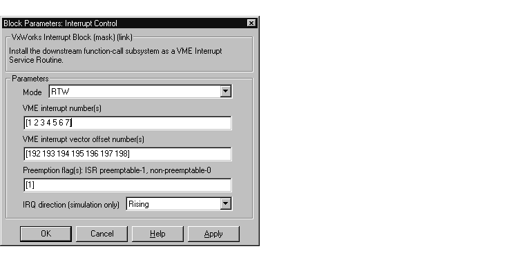
The picture below shows the VxWorks Asynchronous Interrupt block dialog box.

Parameters associated with the Asynchronous Interrupt block are:
In RTW mode, the Real-Time Workshop uses vxinterrupt.tlc to realize asynchronous interrupts in the generated code. The ISR is passed one argument, the root SimStruct, and the Simulink definition of the function-call subsystem is remapped to conform with the information in the SimStruct.
[4 2 5]). intConnect(INUM_TO_IVEC(#),...). You should specify a unique vector offset number for each interrupt number. intLock() and intUnlock() calls to be inserted at the beginning and end of the ISR respectively. This should be used carefully since it increases the system's interrupt response time for all interrupts at the intLockLevelSet() level and below. Asynchronous Interrupt Block Example - Simulation Mode
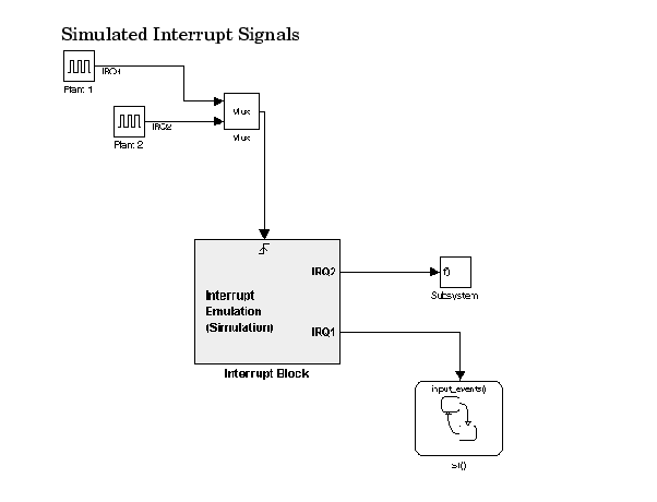
This example shows how the Asynchronous Interrupt block works in simulation mode.

The Asynchronous Interrupt block works as a "handler" that routes signals and sets priority. If two interrupts occur simultaneously, the rule for handling which signal is sent to which port is left to right and top to bottom. This means that IRQ2 receives the signal from Plant 1 and IRQ1 receives the signal from Plant 2 simultaneously. IRQ1 still has priority over IRQ2 in this situation.
Note that the Asynchronous Interrupt block executes during simulation by processing incoming signals and executing downstream functions. Also, interrupt preemption cannot be simulated.
Asynchronous Interrupt Block Example - RTW Mode
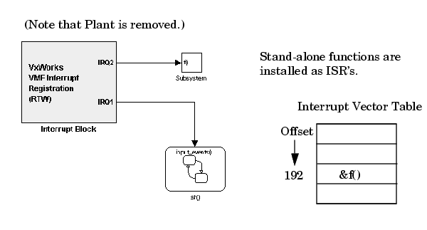
 This example shows the Asynchronous Interrupt block in RTW mode.
In this example, the simulated plant signals that were included in the previous example have been removed. In RTW mode, the Asynchronous Interrupt block receives interrupts directly from the hardware.
During the Target Language Compiler phase of code generation, the Asynchronous Interrupt block installs the code in the Stateflow chart and the Subsystem block as interrupt service routines. Configuring a function-call subsystem as an ISR requires two function calls, int_connect and int_enable. For example, the function f(u) in the Function block requires that the Asynchronous Interrupt block inserts a call to int_connect and sysIntEnable in the mdlStart function, as shown below.
/* model start function */
MdlStart()
{
  . . .
  int_connect(f,192,1);
  . . .
  sysIntEnable(1);
  . . .

}
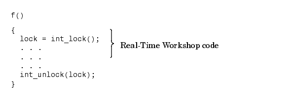
Locking and Unlocking ISRs. It is possible to lock ISRs so that they are not preempted by a higher priority interrupt. Configuring the interrupt as nonpreemptive has this effect. The following code fragment shows where the Real-Time Workshop places the int_lock and int_unlock functions to configure the interrupt as nonpreemptive.

Finally, the model's terminate function disables the interrupt:
/* model terminate function */
MdlTerminate()
{
  ...
  int_disable(1);
  ...
}
 | Interrupt Handling | Task Synchronization Block |  |