| Power System Blockset | |
Description of the Drive System
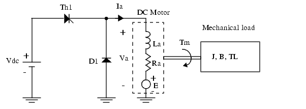
A simplified diagram of the drive system is shown in Figure 2-10. The DC motor is fed by the DC source through a chopper that consists of the GTO thyristor, Th1, and the free-wheeling diode D1. The DC motor drives a mechanical load that is characterized by the inertia J, friction coefficient B, and load torque TL (which can be a function of the motor speed).
Figure 2-10: Chopper-Fed DC Motor Drive
In this diagram, the DC motor is represented by its equivalent circuit consisting of inductor La and resistor Ra in series with the counter electromotive force (emf) E.
The back EMF is proportional to the motor speed

where KE is the motor voltage constant and  is the motor speed.
In a separately excited DC machine, the motor voltage constant KE is proportional to the field current if

where Laf is the field-armature mutual inductance.
The torque developed by the DC motor is proportional to the armature current Ia

where KT is the motor torque constant.
The DC motor torque constant is equal to the voltage constant

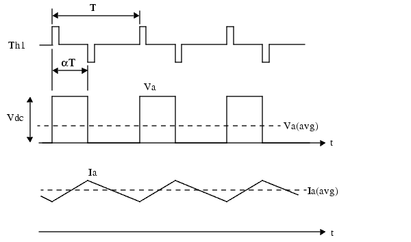
Thyristor Th1 is triggered by a pulse width modulated (PWM) signal to control the average motor voltage. Theoretical waveforms illustrating the chopper operation are shown in Figure 2-11.
Figure 2-11: Waveforms Illustrating the Chopper Operation
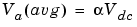
The average armature voltage is a direct function of the chopper duty cycle  :
:
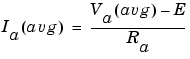
Note that this relation is valid only when the armature current is continuous. In steady-state, the armature average current is equal to:
The peak-to-peak current ripple is
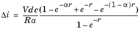
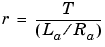
where is the duty cycle and r is the ratio between the chopper period and the DC motor electrical time constant:
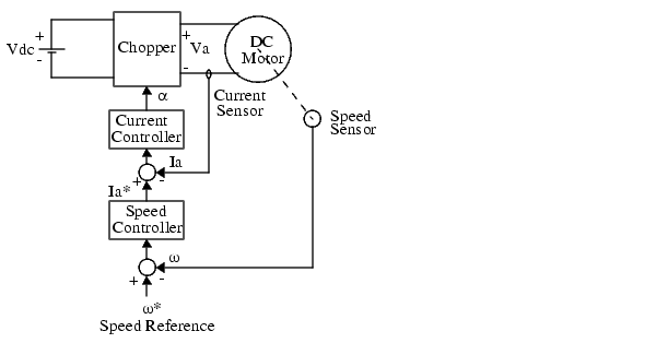
In this case study, we consider a variable-speed DC motor drive using a cascade control configuration. A block diagram of this drive is shown in Figure 2-12.
Figure 2-12: Variable-Speed DC Motor Drive
The motor torque is controlled by the armature current Ia, which is regulated by a current control loop. The motor speed is controlled by an external loop, which provides the current reference Ia* for the current control loop.
| | Chopper-Fed DC Motor Drive | Modeling the DC Drive | |