| Power System Blockset |
  |
Series RLC Load
Implement a linear series RLC load.
Library
Elements
Description
The Series RLC Load block implements a linear load as a series combination of R L C elements. At the specified frequency, the load will exhibit constant impedance and its power will be proportional to the square of the applied voltage. Only elements associated with nonzero powers will be displayed in the block icon.
Dialog Box and Parameters

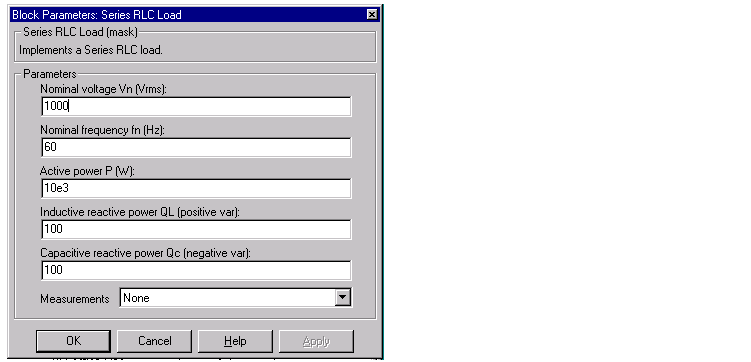
- Nominal voltage Vn
- The nominal voltage of the load, in volts rms.
- Nominal frequency fn
- The nominal frequency, in hertz.
- Active power P
- The active power of the load, in watts.
- Inductive reactive power QL
- The inductive reactive power QL, in vars. Specify a positive value, or zero.
- Capacitive reactive power QC
- The capacitive reactive power QC, in vars. Specify a positive value, or zero.
- Measurements
- Select Branch voltage to measure the voltage across the Series RLC Load block terminals.
- Select Branch current to measure the current flowing through the Series RLC Load block.
- Select Branch voltage and current to measure the voltage and the current of the Series RLC Load block.
- Place a Multimeter block in your model to display the selected measurements during the simulation. In the Available Measurement listbox of the Multimeter block, the measurement will be identified by a label followed by the block name:
Measurement
|
Label
|
Branch voltage
|
ub:
|
Branch current
|
ib:
|
Example
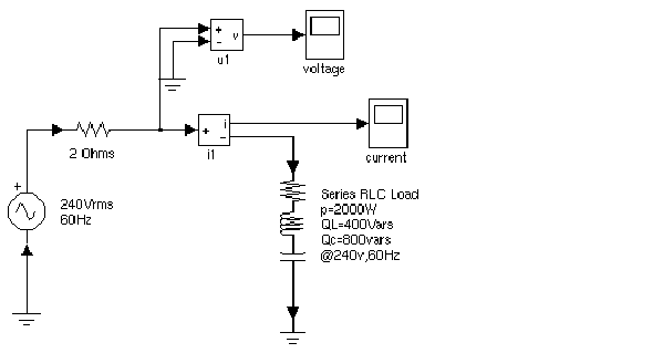
The following circuit uses a Series RLC Load block to implement a simple load. This example is available in the psbseriesload.mdl file.

See Also
Series RLC Branch, Parallel RLC Branch, Parallel RLC Load
 | Series RLC Branch | | Simplified Synchronous Machine |  |


