| Model Predictive Control Toolbox | |
Converts a discrete-time state-space system model into the MPC mod format.
Syntax
pmod=ss2mod(phi,gam,c,d)pmod=ss2mod(phi,gam,c,d,minfo)
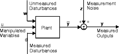
Consider the process shown in the above block diagram. ss2mod assumes the following state-space representation:
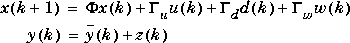
where x is a vector of n state variables, u represents nu manipulated variables, d represents nd measured disturbances, w represents nw unmeasured disturbances, y is a vector of ny plant outputs, z is measurement noise, and  ,
,  u, etc., are constant matrices of appropriate size. The variable
  (k) represents the plant output before the addition of measurement noise. We further define:
D = [Du Dd Dw]
= [u d w]
ss2mod uses the , , C, and D matrices you supply to build a model, pmod, in the MPC mod format. See the mod section for more details.
You can also divide the outputs into nym measured outputs and nyu unmeasured outputs, where nym + nyu = ny. Then the first nym elements in y and the first nym rows in C and D are assumed to be for the measured outputs, and the rest are for the unmeasured outputs.
minfo is an optional variable that allows you to specify certain characteristics of the system. The general form is a row vector with 7 elements, the interpretation of which is as follows:minfo as a scalar, ss2mod takes it as the sampling period and sets the remaining elements of minfo as follows:
In other words, the default is to assume that all inputs are manipulated variables and all outputs are measured. If you omitminfo(2) = # rows in phi,minfo(3) = # columns in gam,minfo(4) =minfo(5) = 0,minfo(6) = # rows in c,minfo(7) = 0.
minfo, ss2mod sets the sampling period to 1 and uses the defaults for the remaining elements.
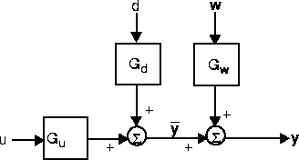
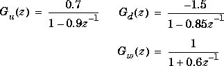
Suppose you have the situation shown in the above diagram where u, d, w, and y are scalar signals, and the three transfer functions are first-order:
ss2mod:
[phiu,gamu,cu,du]=tf2ss(0.7,[1 -0.9]);
[phid,gamd,cd,dd]=tf2ss(-1.5,[1 -0.85]);
[phiw,gamw,cw,dw]=tf2ss(1,[1 0.6]);
[phi,gam,c,d]=mpcparal(phiu,gamu,cu,du,phid,gamd,cd,dd);
[phi,gam,c,d]=mpcparal(phi,gam,c,d,phiw,gamw,cw,dw);
delt=2;
minfo=[delt 3 1 1 1 1 0];
pmod=ss2mod(phi,gam,c,d,minfo)
You must be careful to build up the parallel structure in the correct order. For example, the columns corresponding to
u must always come first in .
Another, more foolproof way is to use the addmd and addumd functions:
ny=1;
gu=poly2tfd(0.7,[1 -0.9],delt);
gd=poly2tfd(-1.5,[1 -0.85],delt);
gw=poly2tfd(1,[1 0.6],delt);
pmod=tfd2mod(delt,ny,gu);
pmod=addmd(pmod,tfd2mod(delt,ny,gd));
pmod=addumd(pmod,tfd2mod(delt,ny,gw))
Using either approach, the result is:
pmod =
2.0000   3.0000   1.0000   1.0000   1.0000   1.0000     0
NaN      0.9000   0        0        1.0000   0          0
0        0        0.8500   0        0        1.0000     0
0        0        0       -0.6000   0        0          1.0000
0        0.7000  -1.5000   1.0000   0        0          0
See Also
mod format, mod2ss
| smpcsim | ss2step | |