| Fixed-Point Blockset |
  |
Lead Filter or Lag Filter Realization
This section presents the realization for a lead filter or lag filter. The transfer function and difference equation, block parameters, and model design are discussed.
The FixPt Lead or Lag Filter is approximated by the z-domain transfer function
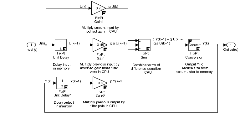
where K is the DC gain, a is a zero on the unit circle, and p is a pole on the unit circle. The realization is shown below.

As shown in the figure, the transfer function yields the difference equation
where k is the current time step, k - 1 is the previous time step, g = K(1 - p) is the modified gain, y(k) is the current output, y(k - 1) is the output from the previous time step, u(k) is the current input, and u(k - 1) is the input from the previous time step.
Parameters and Dialog Box
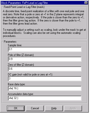
The dialog box and parameter descriptions for the lead or lag filter realization are given below.

- Sample time
The time interval, Ts, between samples
- Pole of filter
The pole, p, defined in the z-plane. A pole at +1 represents integral action
- Zero of filter
The zero, a, defined in the z-plane. A zero at +1 represents derivative action
- DC gain
The constant gain, K
- Base data type
The processor's base data type
- Accumulator data type
The processor's accumulator data type
Model Design Review
A brief review of the model design is given below. The design criteria reflect the rules presented in Design Rules.
- The gains involve multiplications which are a size-growing operation. In most cases, it is desirable for gains and inputs to use the word size given by the Base data type or smaller. The output can be left at the Accumulator data type for extra precision in subsequent operations. Alternatively, if the output were stored in RAM, or used by a size-growing operation, it could be reduced to the Base data type.
- The FixPt Sum block converts inputs to the output data type before performing the actual addition. Given this order of operation, using Accumulator data type often gives better precision.
- The FixPt Conversion block forces the output to the Base data type before storage in RAM (before input to the unit delay). Converting the output in the feed forward part of the realization prevents subsequent operations from being burdened with a large data type.
 | Derivative | | State-Space Realization |  |


