
| DSP Blockset |   |
Design and implement a raised cosine FIR filter.
Library
Filtering / Filter Designs
Description
The Digital FIR Raised Cosine Filter Design block uses the firrcos function in the Signal Processing Toolbox to design a lowpass, linear-phase, digital FIR filter with a raised cosine transition band. The block applies the filter to a discrete-time input using the Direct-Form II Transpose Filter block.
An M-by-N sample-based matrix input is treated as M*N independent channels, and an M-by-N frame-based matrix input is treated as N independent channels. In both cases, the block filters each channel independently over time, and the output has the same size and frame status as the input.
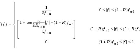
The frequency response of the raised cosine filter is

where H(f) is the magnitude response at frequency f, fn0 is the normalized cutoff frequency (-6 dB) specified by the Upper cutoff frequency parameter, and R is a rolloff factor in the range [0,1] determining the passband-to-stopband transition width.
The Square-root raised cosine filter option designs a filter with magnitude response  . This is useful when the filter is part of a pair of matched filters.
When the Design method parameter is set to Rolloff factor, the secondary Rolloff factor parameter is enabled, and R can be directly specified. When Design method is set to Transition bandwidth, the secondary Transition bandwidth parameter is enabled, and the transition region bandwidth,  f, can be specified in place of R. The transition region is centered on fn0 and must be sufficiently narrow to satisfy

The Upper cutoff frequency and Transition bandwidth parameter values are normalized to half the sample frequency.
The Window type parameter allows you to apply a variety of different windows to the raised cosine filter. See the Window Function block reference for a complete description of the available options.
Algorithm
The filter output is computed by convolving the input with a truncated, delayed, windowed version of the filter's impulse response. The impulse response for the raised cosine filter is


The impulse response for the square-root raised cosine filter is


Dialog Box
1 specifies half the sample frequency. Tunable. . Tunable.
 f, enabled when Transition bandwidth is selected in the Design method parameter. Tunable.
 parameter. Increasing
  widens the mainlobe and decreases the amplitude of the window sidelobes in the window's frequency magnitude response. Tunable.
References
Proakis, J. G. Digital Communications. Third ed. New York, NY: McGraw-Hill, 1995.
Proakis, J. G. and M. Salehi. Contemporary Communication Systems Using MATLAB. Boston, MA: PWS Publishing, 1998.
See Also
| Digital FIR Filter Design |
DSP Blockset |
| Digital IIR Filter Design |
DSP Blockset |
| Direct-Form II Transpose Filter |
DSP Blockset |
| Least Squares FIR Filter Design |
DSP Blockset |
| Remez FIR Filter Design |
DSP Blockset |
| Window Function |
DSP Blockset |
| Yule-Walker IIR Filter Design |
DSP Blockset |
firrcos |
Signal Processing Toolbox |
See Filter Designs for related information.
 | Digital FIR Filter Design | Digital IIR Filter Design |  |