

| Dials & Gauges Blockset | |
Modifying ActiveX Control Properties
You modify ActiveX control properties in one of these ways:
Modifying the Range Displayed on an ActiveX Control
Changing the range of values displayed on an ActiveX control involves adjusting these ActiveX control properties:
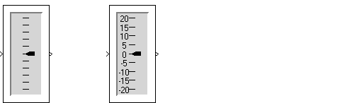
-20 to 20, sets the interval between tick marks to 5, and shows the tick mark labels. This figure shows the Generic Linear Gauge with its default settings (left) and with modified settings (right).
Modifying the Scale Properties
Click on the Scales tab to display the scales properties page. This figure shows the default scale properties for the Generic Linear Gauge.
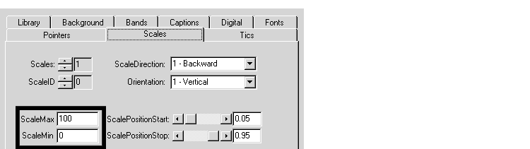
To modify the scale range, change ScaleMax to 20 and ScaleMin to -20.
Modifying the Tick Mark Properties
Click on the Tics tab to display the tick mark properties page. This figure shows the default tick mark properties.
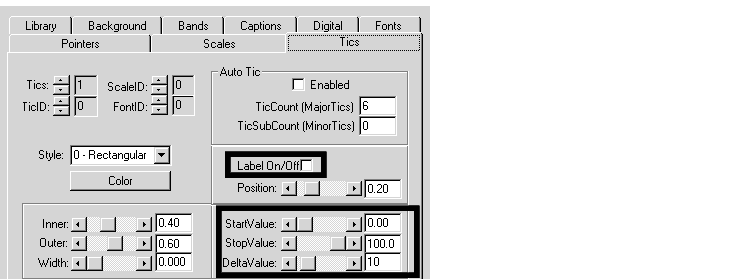
To show tick mark labels, check the Label On/Off check box.
To set the starting and ending tick marks so they mark the minimum and maximum scale settings, setStartValue to -20 and StopValue to 20. Change the DeltaValue property, which sets the spacing between tick marks. A value of 5 is reasonable for default control size.
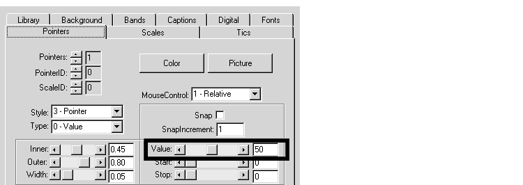
Modifying the Needle or Pointer Properties
Click on the Pointers tab to display the pointer properties page. This figure shows the default pointer properties.
 .
.
The Value property indicates the current pointer value. Set the initial value to 0, halfway between the maximum and minimum scale values.
Modifying Multiple Tick Marks
Some characteristics can be repeated in an ActiveX control. For example, a single ActiveX control can display multiple needles or tick marks.
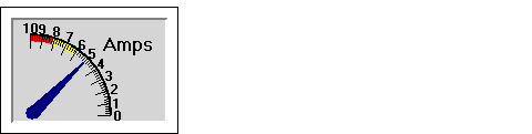
The first set consists of 11 longer tick marks, each positioned at one of the label values, positioned at increments of 1.0. The second set consists of five shorter tick marks for each integer change in the scale, positioned at increments of 0.2.
To examine how these tick marks have been created, double-click on the Amp Meter control to display its properties dialog box. Select the Tics tab.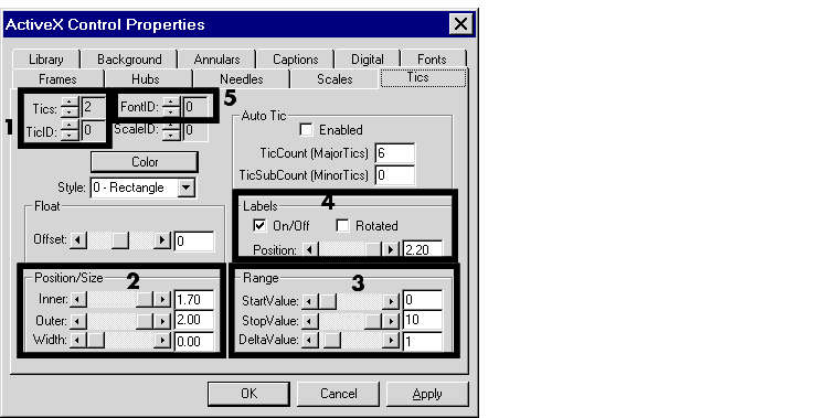
The Tics and TicID properties, in the box labeled 1, are defined as follows:
Tics property specifies how many sets of tick marks are used by the control. For this control, this property is set to 2.
TicID property indicates which set of tick marks is defined by the other properties on this page. When specifying the characteristics of a set of tick marks, you set the TicID property, and then define the property values for that set of tick marks. In the dialog box page above, the settings for all the properties on the page apply to the first set, identified as TicID 0.
| Note When defining multiple components, the first instance is identified by an ID of 0. In this example, the two sets of tick marks have IDs of 0 and 1. |
Position/Size properties, in the box labeled 2, are defined as follows:
Inner property defines the edge of the tick mark closest to the needle center and the Outer property defines the edge of the tick mark farthest from the needle center. To see where the tick marks are located relative to the needle length, examine the needle length by selecting the Needles page. The needle length is 2.0. The Inner position is 1.70 and the Outer position is 2.00. These tick marks are 0.3 units long.
Width of the tick marks is 0.00, the narrowest width.
Range properties, in the box labeled 3, are defined as follows:
StartValue determines at which scale value the first tick mark is displayed. For these tick marks, the value is 0.
StopValue determines at which scale value the last tick mark is displayed. For these tick marks, the value is 10.
DeltaValue determines the interval between tick marks. For these tick marks, the value is 1.
Labels properties On/Off check box, in the box labeled 4, determines whether the labels are displayed. For the first set of tick marks, the labels are displayed.
The FontID property, in the box labeled 5, determines which of multiple fonts defined for this control is used for the label. In this case, two font sets are defined. The first (FontID 0) is for the tick marks, the second (FontID 1) is for the caption, "Amps."
To examine the second set of tick marks, change the TicID property value to 1 by clicking on the up arrow to the left of the value. The Tics page looks like this.
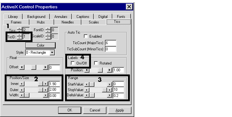
The Position/Size properties, in the box labeled 2, are defined as follows:
Inner position is 1.90 and the Outer position is 2.00. These tick marks are 0.10 units long, one-third the length of the longer tick marks.
Width of the tick marks is 0.00, the same as the longer tick marks.
Range properties, in the box labeled 3, are defined as follows.
StartValue for these tick marks is 0. The first short tick mark and the first long tick mark appear in the same place.
StopValue for these tick marks is 10. The last short tick mark and the last long tick mark appear in the same place.
DeltaValue determines the interval between tick marks. For these tick marks, the value is 0.2.
Labels properties On/Off check box determines whether the labels are displayed. For this set of tick marks, the labels are not displayed.
Saving a Customized ActiveX Control
To save a modified ActiveX control for later use, follow these steps:
| Note: If you leave this field blank, the new ActiveX control properties write over the previous settings, which means that you cannot access the original version except by reinstalling the blockset. |
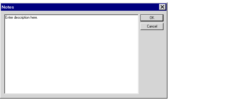
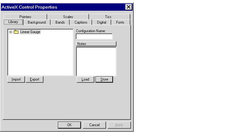
The figure below shows the dialog box with fields filled in. The modified
ActiveX control configuration will be stored in the Linear Gauge directory.
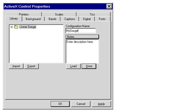
.ax files, which other users can access. You can also export configurations to .gms files for sharing. To do this, select a directory in the directory hierarchy and click Export. You can later use Import to access these configurations.
| | Using ActiveX Control Blocks in a Model | Advanced Topics | |