sisotool
Purpose
Initialize the SISO Design Tool
Syntax
sisotool
sisotool(plant)
sisotool(plant,comp)
sisotool(views)
sisotools(views,plant,comp)
sisotool(views,plant,comp,options)
Description
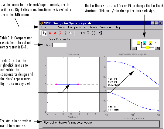
When invoked without input arguments, sisotool initializes a SISO Design GUI for interactive compensator design. This GUI allows you to design a single-input/single-output (SISO) compensator using root locus and Bode diagram techniques.
This picture shows the SISO Design Tool.
sisotool(plant) opens the SISO Design Tool with plant imported. If your
plant is any SISO LTI object (created with ss, tf, or zpk) that exists in the
MATLAB workspace, sisotool(plant)
initializes a SISO Design Tool with the plant model P set to plant. The SISO Design Tool draws the root locus of the closed-lop poles and zeros. The Bode diagram plots the open-loop frequency response (both magnitude and phase) of the plant.
sisotool(plant,comp)
also initializes a SISO Design Tool for the plant model plant. In addition, the root locus compensator is initialized to comp, where comp is any SISO LTI object that exists in the MATLAB workspace.
By default, the SISO Design Tool:
sisotool(views) or sisotool(views,plant,comp) specifies the initial configuration of the SISO Design Tool. The parameter views can be any of the following strings (or combination thereof):
'rlocus' -- Root Locus plot'bode' -- Bode diagrams of the open-loop response sisotool('bode')
opens a SISO Design Tool with only the Bode Diagrams on.
sisotool(plant,comp,options) allows you to override the default compensator location and feedback sign by using an extra input argument options with the following fields:
options.Location = 'forward' -- Compensator in the forward loopoptions.Location = 'feedback' -- Compensator in the feedback loopoptions.Sign = -1 -- Negative feedbackoptions.Sign = 1 -- Positive feedbackYou can design compensators for one of the following two feedback loop configurations. 
Figure 1-1: The SISO Design Tool Supports Two Feedback Structures.
In either configuration, F is a pre-filter, P is the plant model, H is the sensor dynamics, and K is the compensator to be designed. In terms of the GUI design procedure, once you specify them, F, P, and H are fixed in the feedback structure. The default structure is for the compensator to be in the forward path.
See Also
bode Select gain from the root locus plot
ltiview Open an LTI Viewer
rlocus Plot root locus