
| Stateflow |   |
Defining Function Call Output Events
These are essential conditions that define the use of function call output events:
Output to Simulink event with a Function Call trigger type defined (added and defined using either the graphics editor Add menu or the Explorer. See Defining Output Events.)Output to Simulink function call event has the Trigger type field set to function-call.Example: Using Function Call Output Events
A function call trigger operates essentially like a programming subroutine call. When the system executes the step where the function call is specified, the triggered subsystem executes and then returns to the next statement in the execution sequence. Using function call triggers, the Stateflow block can control the execution of other Simulink blocks in the model.
Use a function call event output when you want a Stateflow block (logic portion/control flow) to control one or more Simulink blocks (algorithmic portion/data flow).
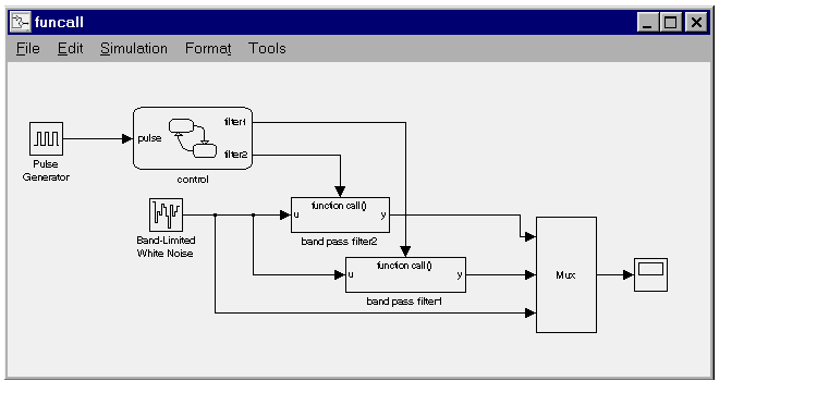
This example shows a use of function call output events.

The control block is a Stateflow block that has one data input called pulse and two event Function Call outputs called filter1 and filter2. A pulse generator provides input data to the control block. Within the control block, a determination is made whether to make a function call to filter1 or filter2. If, for example, the Output to Simulink event Function Call filter1 is broadcast, the band pass filter1 block executes and then returns to the next execution step in the control block. As part of its execution, band pass filter1 receives unfiltered input data and outputs filtered data for display on a scope.
The Stateflow block controls the execution of band pass filter1 and band pass filter2.
Example: Function Call Semantics
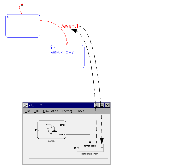
In this example the transition from state A to state B (in the Stateflow diagram) has a transition action that specifies the broadcast of event1. event1 is defined in Stateflow to be an Output to Simulink with a Function Call trigger type.The Stateflow block output port for event1 is connected to the trigger port of the band pass filter1 Simulink block. The band pass filter1 block has its Trigger type field set to Function Call.

This sequence is followed when state A is active and the transition from state A to state B is valid and is taken:
A exit actions execute and complete.
A is marked inactive.
event1. Because event1 is an event Output to Simulink with a function call trigger, the band pass filter1 block executes and completes, and then returns to the next statement in the execution sequence. The value of y is fed back to the Stateflow diagram.
B is marked active.
B entry actions execute and complete (x = x + y). The value of y is the updated value from the band pass filter1 block.
 | Defining Output to Simulink Event Triggers | Defining Edge-Triggered Output Events |  |