
| Stateflow |   |
Defining a Continuous Stateflow Block
To define a continuous Stateflow block, the chart Update method (set in the Chart Properties dialog box) is set to Continuous. (See Specifying Chart Properties)
Considerations in Choosing Continuous Update
The availability of intermediate data makes it possible for the solver to `back up' in time to precisely locate a `zero crossing'. Refer to Using Simulink for further information on zero crossings. Use of the intermediate time point information can provide increased simulation accuracy.
To support the Continuous update method, Stateflow keeps an extra copy of all its data.
In most cases, including continuous-time simulations, the Inherited method provides consistent results. The timing of state and output changes of the Stateflow block is entirely consistent with that of the continuous plant model.
There are situations when changes within the Stateflow block must be felt immediately by the plant and a Continuous update is needed:
Output to Simulink that is a direct function of data Input from Simulink and the data is updated by the Stateflow diagram (state during actions in particular).Example: Continuous Stateflow Block
Simulink will awaken (sample) the Stateflow block at each step in the simulation, as well as at intermediate time points that may be requested by the Simulink solver. This method is consistent with the continuous method in Simulink.
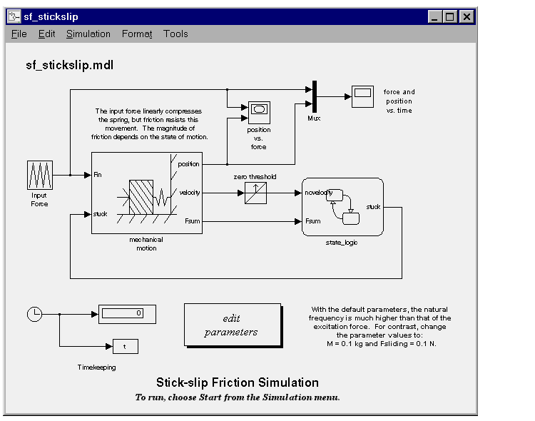
In this example (provided in the Examples/Stick Slip Friction Demonstration block), the chart Update method (set in the Chart Properties dialog box) is set to Continuous.

 | Defining an Inherited Stateflow Block | Defining Output to Simulink Event Triggers |  |