
| Stateflow |   |
Defining a Sampled Stateflow Block
There are two ways you can define a sampled Stateflow block. Setting the chart Update method (set in the Chart Properties dialog box) to Sampled and entering a Sample Time value defines a sampled Stateflow block. (See Specifying Chart Properties.)
Alternatively, you can add and define an Input from Simulink data object. Data is added and defined using either the graphics editor Add menu or the Explorer. (See Defining Input Data.) The chart sample time is determined by Simulink to be consistent with the rate of the incoming data signal.
The Sample Time (set in the Chart Properties dialog box) takes precedence over the sample time of any Input from Simulink data.
Example: Sampled Stateflow Block
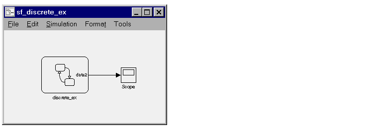
A Stateflow block that is not explicitly triggered via the trigger port can be triggered by Simulink by specifying a discrete sample rate. You can specify a Sample Time in the Stateflow diagram's Chart properties dialog box. The Stateflow block is then called by Simulink at the defined, regular sample times.

The outputs of a sampled Stateflow block are held after the execution of the block.
 | Defining a Triggered Stateflow Block | Defining an Inherited Stateflow Block |  |