| Using Simulink |
  |
Logical Operator
Perform the specified logical operation on the input.
Library
Math
Description

The Logical Operator block performs any of these logical operations on its inputs: AND, OR, NAND, NOR, XOR, and NOT. The output depends on the number of inputs, their dimensionality, and the selected operator. The output is 1 if TRUE and 0 if FALSE. The block icon shows the selected operator. The following rules apply to the inputs and outputs of the block:
- If the block has more than one input, any nonscalar inputs must have the same dimensions. For example, if any input is a 2-by-2 array, all other nonscalar inputs must also be 2-by-2 arrays.
- Scalar inputs are expanded to have the same dimensions as the nonscalar inputs.
- If the block has more than one input, the output has the same dimensions as the inputs (after scalar expansion) and each output element is the result of applying the specified logical operation to the corresponding input elements. For example, if the specified operation is AND and the inputs are 2-by-2 arrays, the output is a 2-by-2 array whose top, left element is the result of applying AND to the top, left elements of the inputs, etc.
- If the block has a single input and the specified operator is not the NOT operator, the input must be vector-like, i.e. a scalar, a 1-D array, or a one-row or one-column 2-D array. The output is a scalar value equal to the result of applying the operation to the elements of the input.
- If the specified operation is NOT, the block accepts only one input. The output has the same dimensions as the input and contains the logical complements of the elements of the input.
When configured as a multi-input XOR gate, this block performs an addition modulo two operation as mandated by the IEEE standard for logic elements.
Data Type Support
A Logical Operator block accepts only signals of type boolean on its input ports, if Boolean logic signals are enabled (see Enabling Strict Boolean Type Checking). Otherwise, the block also accepts inputs of type double. A nonzero input of type double is treated as TRUE (1), a zero input as FALSE (0). All inputs must be of the same type. The output of the block is of the same type as the input.
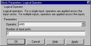
Parameters and Dialog Box

- Operator
- The logical operator to be applied to the block inputs. Valid choices are the operators listed above.
- Number of input ports
- The number of block inputs. The value must be appropriate for the selected operator.
Characteristics
Direct Feedthrough
|
Yes
|
Sample Time
|
Inherited from driving block
|
Scalar Expansion
|
Of inputs
|
Dimensionalized
|
Yes
|
Zero Crossing
|
No
|
 | Interpolation (n-D) Using PreLook-Up | | Look-Up Table |  |


