| Power System Blockset |
  |
Three-Phase Transformer (Two Windings)
Implement a three-phase transformer with configurable winding connections.
Library
Elements
Description
This block implements a three-phase transformer using three single-phase transformers. The saturable core can be simulated or not, simply by setting the appropriate checkbox in the parameter menu of the block. See the Linear Transformer block and Saturable Transformer block sections for a detailed description of the electrical model of single-phase transformers.
The two windings of the transformer can be connected in the following manner.
- Wye
- Wye with accessible neutral
- Grounded Wye
- Delta (D11), delta leading wye by 30 degrees
- Delta (D1), delta lagging wye by 30 degrees
| Note
The D11 and D1 convention assumes that the wye voltage phase angle
is at noon (12), on a clock display. D1 and D11 refer respectively to 11 AM (-30
degrees) and 1 PM (+30 degrees)
|
The block takes into account the connection type you have selected and the icon of the block is automatically updated. An input port labeled N is added to the block if you select the wye connection with accessible neutral for the winding 1. If you ask for an accessible neutral on winding 2 an extra outport port labeled n is generated.
The following icons are displayed for four arbitrary settings
The saturation characteristic, when activated, is the same as the one described for the saturable transformer block and the icon of the block is automatically updated. If the fluxes are not specified, the initial values will be automatically adjusted so that the simulation starts in steady state.
The leakage inductance and resistance of each winding is given in p.u. based on the transformer nominal power Pn and on the nominal voltage of the winding (V1 or V2). Refer to the per unit explanations given in the Linear Transformer and Saturable Transformer blocks reference sections.
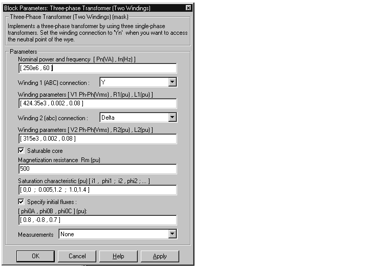
Dialog Box and Parameters

- Nominal power and frequency
- The nominal power rating, in volt amperes (VA), and nominal frequency, in hertz (Hz), of the transformer.
- Winding 1 (ABC) connection
- The phase connection for the winding 1.
- Winding parameters
- The phase-to-phase nominal voltage in volts rms, resistance, and leakage inductance in p.u. for the winding 1.
- Winding 2 (abc) connection
- The phase connection for the winding 2.
- Winding parameters
- The phase-to-phase nominal voltage in volts rms, resistance, and leakage inductance in p.u. for the winding 2.
- Saturable core
- If checked, implements a saturable three-phase transformer.
- Magnetization resistance Rm
- The magnetization resistance Rm, in p.u.
- Magnetization reactance Lm
- The magnetization inductance Lm, in p.u., for a non-saturable core. The Magnetization reactance Lm parameter is not visible in the dialog box if the Saturable core parameter is checked.
- Saturation characteristic
- The saturation characteristic for the saturable core. Specify a serie of current/ flux pairs (in p.u.) starting with the pair (0,0). This parameter is visible only if the Saturable core parameter is checked.
- Specify initial fluxes
- if checked, the initial fluxes are defined by the
[phi0A, phi0B, phi0C] parameter
- [phi0A, phi0B, phi0C]
- Specifies initial fluxes for each phase of the transformer. This parameter is visible only if the Specify initial fluxes and Saturable core parameters are checked.
- Measurements
- Select Winding voltages to measure the voltage across the winding terminals of the Three-Phase Transformer block.
- Select Winding currents to measure the current flowing through the windings of the Three-Phase Transformer block.
- Select Fluxes and magnetization currents to measure the flux linkage, in volt seconds (V.s), and the magnetization current (for saturable transformers only).
- Select All measurement (V, I, Flux) to measure the winding voltages, currents, magnetization currents, and the fluxes.
- Place a Multimeter block in your model to display the selected measurements during the simulation. In the Available Measurement listbox of the Multimeter block, the measurements will be identified by a label followed by the block name.
- If the Winding 1 ABC connection parameter is set to Y, Yn, or Yg , the labels will be as follows.
Measurement
|
Label
|
Winding voltages
|
Uan_w1: , Ubn_w1: , Ucn_w1:
or :
Uag_w1: , Ubg_w1: , Ucg_w1:
|
Winding currents
|
Ian_w1: , Ibn_w1: , Icn_w1:
or :
Iag_w1: , Ibg_w1: , Icg_w1:
|
Fluxes
|
Flux A: , Flux B: , Flux C:
|
Magnetization currents
|
Imag A: , Imag B: , Imag C:
|
- If the Winding 1 ABC connection parameter is set to Delta (D11) or Delta (D1), the labels will be as follows.
Measurement
|
Label
|
Winding voltages
|
Uab_w1: , Ubc_w1: , Uca_w1:
|
Winding currents
|
Iab_w1: , Ibc_w1: , Ica_w1:
|
Fluxes
|
Flux A: , Flux B: , Flux C:
|
Magnetization currents
|
Imag A: , Imag B: , Imag C:
|
The same labels apply for the Winding 2 (abc) connection parameter, except that 1 is replaced by 2 in the labels.
Example
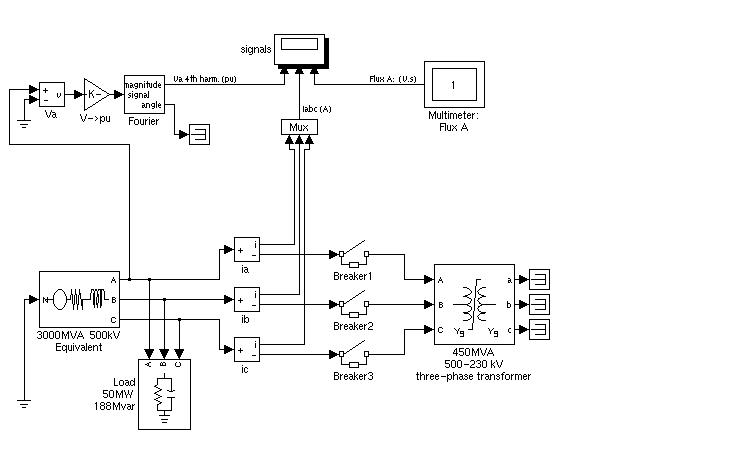
The psbtransfo3ph.mdl circuit is using the Three-Phase Transformer block where the saturable core is simulated. Both windings are connected in a wye grounded configuration. Note that the neutral points of the two windings are internally connected to the ground. 
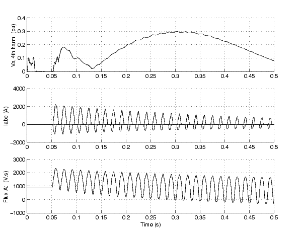
Run the simulation and observe the simulation results.

See Also
Three-Phase Transformer (Three Windings)
 | Synchronous Machine | | Three-Phase Transformer (Three Windings) |  |


![]()


