| MOTDSP563 Blockset |
|
Search Help Desk |
| MOTDSP563 FIR Decimation | Contents See Also |
Purpose
Filter and downsample an input signal.
Library
Motdsp563lib
Description
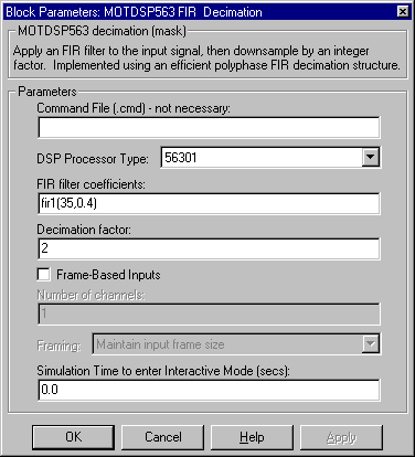
The MOTDSP563 FIR Decimation block resamples the input at an integer rate K times slower than the input sample rate, where K is specified by the Decimation factor parameter. This process consists of two steps:
The MOTDSP563 FIR Decimation block implements the FIR filtering and downsampling steps together using a polyphase filter structure, which is more efficient than straightforward filter-then-decimate algorithms. The output of the decimator is the first filter phase.
In practice, the filter specified by the FIR filter coefficients vector should be a lowpass FIR with normalized cutoff frequency no greater than 1/K. The coefficients in the vector are ordered in descending powers of z.
The Frame-based inputs parameter allows you to choose between sample-based and frame-based operation.
Sample-Based Operation
When the check box is not selected (default), the block assumes that the input is a 1-by-N sample vector or M-by-N sample matrix. Each of the N vector elements (or M*N matrix elements) is treated as an independent channel, and the block decimates each channel over time.
Frame-Based Operation
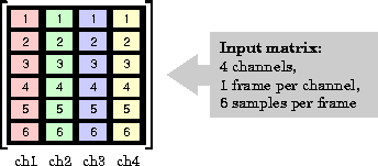
When the Frame-based inputs check box is selected, the block assumes that the input is an M-by-N frame matrix. Each of the N frames in the matrix contains M sequential time samples from an independent signal. The illustration below shows a 6-by-4 matrix input:
The Number of channels parameter specifies the number of independent channels (columns), N, in the matrix, and the block decimates each channel independently over time. Frame-based operation provides substantial increases in throughput rates, at the expense of greater model latency.
In frame-based operation, the Framing parameter determines how the block adjusts the rate at the output. There are two available options:
The block generates the output at the slower (decimated) rate by using a proportionally smaller frame size than the input. For decimation by a factor of K, the output frame size is K times smaller than the input frame size, but the input and output frame rates are equal. The input frame size must be a multiple of the decimation factor.
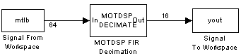
The example below shows a single-channel input of frame size 64 being decimated by a factor of 4 to a frame size of 16. The block's input and output frame rates are identical.
The block generates the output at the slower (decimated) rate by using a proportionally longer frame period at the output port than at the input port. For decimation by a factor of K, the output frame period is K times longer than the input frame period, but the input and output frame sizes are equal.
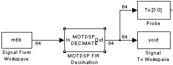
The example below shows a single-channel input (frame size = 64) with a sample period of 1 second being decimated by a factor of 3 to a sample period of 3 seconds. The input and output frame sizes are identical.
Latency
Zero Latency. The FIR Decimation block has zero tasking latency for all single-rate operations. The block is single-rate for the particular combinations of sampling mode and parameter settings shown in the table below.
| Sampling Mode | Parameter Settings |
| Sample-based | Decimation factor parameter, K, is 1. |
| Frame-based | Decimation factor parameter, K, is 1, or Framing parameter is Maintain input frame rate. |
Note that in sample-based mode, single-rate operation occurs only in the trivial case of factor-of-1 decimation.
The block also has zero latency for sample-based multirate operations in Simulink's single-tasking mode. Zero tasking latency means that the block propagates the first filtered input sample (received at t=0) as the first output sample, followed by filtered input samples K+1, 2K+1, and so on.
Nonzero Latency. The FIR Decimation block is multirate for all settings other than those in the above table. The amount of latency for multirate operation depends on Simulink's tasking mode and the block's sampling mode, as shown in the table below.
| Multirate... | Sample-Based Latency | Frame-Based Latency |
| Single-tasking | None | One frame (Mi samples) |
| Multitasking | One sample | One frame (Mi samples) |
In cases of one-sample latency, a zero initial condition appears as the first output sample in each channel. The first filtered input sample appears as the second output sample, followed by filtered input samples K+1, 2K+1, and so on.
In cases of one-frame latency, the first Mi output rows contain zeros, where Mi is the input frame size. The first filtered input sample (first filtered row of the input matrix) appears in the output as sample Mi+1, followed by filtered input samples K+1, 2K+1, and so on. See the example below for an illustration of this case.
See "Excess Algorithmic Delay (Tasking Latency)" in Chapter 2 and "The Simulation Parameters Dialog Box" in Chapter 4 of Using Simulink for more information about block rates and Simulink's tasking modes.
Example
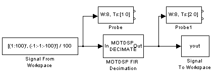
Construct the frame-based model shown below.
Adjust the block parameters as follows.
Configure the Signal From Workspace block to generate a two-channel signal with frame size of 4 and sample period of 0.25. This represents an output frame period of 1 (0.25*4). The first channel should contain the positive ramp signal 1, 2, ..., 100, and the second channel should contain the negative ramp signal -1, -2, ..., -100.
Configure the FIR Decimation block to decimate the two-channel input by decreasing the
output frame rate by a factor of 2 relative to the input frame rate. Use a
third-order filter with normalized cutoff frequency, fn0,
of 0.25. (Note that fn0 satisfies fn0
![]() 1/K.)
1/K.)
Configure the Signal To Workspace block for the two-channel input.
Configure the Probe blocks by deselecting the Probe width and Probe complex signal check boxes (if desired).
This model is multirate because there are at least two distinct sample rates, as shown
by the two Probe blocks. To run this model in Simulink's multitasking mode, select Fixed-step
and discrete from the Type controls in the Solver
panel of the Simulation Parameters dialog box, and select MultiTasking
from the Mode parameter. Also set the Stop time
to 30.
Run the model and look at the output, yout. The first few samples of each
channel are shown below.
yout =
                  0                  0
                  0                  0
                  0                  0
                  0                  0
   0.00038576126099  -0.00038576126099
   0.01500010490417  -0.01500010490417
   0.03499984741211  -0.03499984741211
   0.05500006675720  -0.05500006675720
   0.07500004768372  -0.07500004768372
   0.09500002861023  -0.09500002861023
   0.11500000953674  -0.11500000953674
Since we ran this frame-based multirate model in multitasking mode, the first four (Mi) output rows are zero. The first filtered input matrix row appears in the output as sample 5 (i.e., sample Mi+1).
The filter coefficient vector generated by fir1(3,0.25) is
[0.0386 0.4614 0.4614 0.0386]
or, equivalently,
Dialog Box
| MOTDSP563 FIR Interpolation | FIR interpolation |