
| Data Acquisition Toolbox |   |
Device-Specific Hardware Triggers
Many data acquisition devices possess the ability to accept a hardware trigger. Hardware triggers are processed directly by the hardware and can be either a digital signal or an analog signal. Hardware triggers are often used when speed is required since a hardware device can process an input signal much faster than software.
The device-specific hardware triggers are presented to you as additional property values. Hardware triggers for National Instruments, ComputerBoards, and Agilent Technologies devices are discussed below and in Chapter 10, Base Property Reference.
Note that the available hardware trigger support depends on the board you are using. Refer to your hardware documentation for detailed information about its triggering capabilities.
National Instruments
When using National Instruments (NI) hardware, there are additional trigger types and trigger conditions available to you. These device-specific property values fall into two categories: hardware digital triggering and hardware analog triggering.
The device-specific trigger types and trigger conditions are described below and in Chapter 10, Base Property Reference.
Hardware Digital Triggering. If TriggerType is HwDigital, the trigger occurs when the falling edge of a digital (TTL) signal is detected. The following example illustrates how to configure a hardware digital trigger.
ai = analoginput('nidaq',1);
addchannel(ai,0:7);
set(ai,'TriggerType','HwDigital')
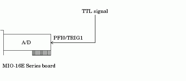
The diagram below illustrates how you connect a digital trigger signal to an MIO-16E Series board. PFI0/TRIG1 corresponds to pin 11.

Hardware Analog Triggering. If TriggerType is HwAnalogPin, the trigger is given by a low-range analog signal (typically between -10 to 10 volts). For example, to trigger your acquisition when the trigger signal is between -4 volts and 4 volts
ai = analoginput('nidaq',1);
addchannel(ai,0:7);
set(ai,'TriggerType','HwAnalogPin')
set(ai,'TriggerCondition','InsideRegion')
set(ai,'TriggerConditionValue',[-4.0 4.0])
If TriggerType is HwAnalogChannel, the trigger is given by an analog signal and the trigger channel is defined as the first channel in the channel group (MATLAB index of one). The valid range of the analog trigger signal is given by the full-scale range of the trigger channel. The following example illustrates how to configure such a trigger where the trigger channel is assigned the descriptive name TrigChan and the default TriggerCondition property value is used.
ai = analoginput('nidaq',1);
addchannel(ai,0:7);
set(ai.Channel(1),'ChannelName','TrigChan')
set(ai,'TriggerType','HwAnalogChannel')
set(ai,'TriggerConditionValue',0.2)
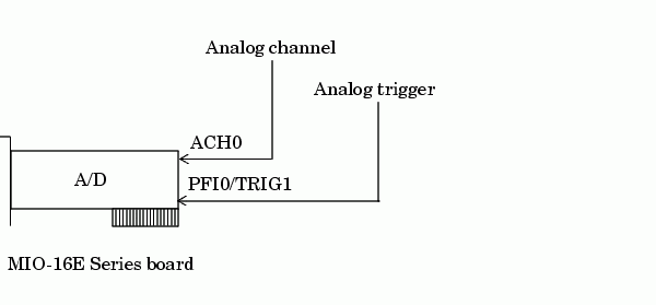
The diagram below illustrates how you can connect analog trigger signals to an MIO-16E Series board.

ComputerBoards
When using ComputerBoards (Measurement Computing Corporation) hardware, there are additional trigger types and trigger conditions available to you. These device-specific property values fall into two categories: hardware digital triggering and hardware analog triggering.
The device-specific trigger types and trigger conditions are described below and in Chapter 10, Base Property Reference.
Hardware Digital Triggering. If TriggerType is HwDigital, the trigger is given by a digital (TTL) signal. For example, to trigger your acquisition when the positive edge of a digital signal is detected
ai = analoginput('cbi',1);
addchannel(ai,0:7);
set(ai,'TriggerType','HwDigital')
set(ai,'TriggerCondition','TrigPosEdge')
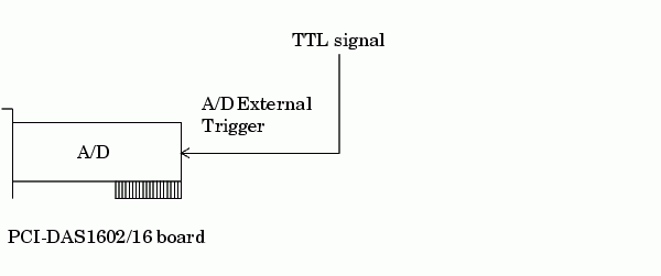
The diagram below illustrates how you connect a digital trigger signal to a PCI-DAS1602/16 board. A/D External Trigger corresponds to pin 45.

Hardware Analog Triggering. If TriggerType is HwAnalog, the trigger is given by an analog signal. For example, to trigger your acquisition when the trigger signal is between -4 volts and 4 volts
ai = analoginput('cbi',1);
addchannel(ai,0:7);
set(ai,'TriggerType','HwAnalog');
set(ai,'TriggerCondition','GateInWindow');
set(ai,'TriggerConditionValue',[-4.0 4.0]);
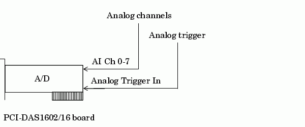
The diagram below illustrates how you connect an analog trigger signal to a PCI-DAS1602/16 board. AI Ch 0-7 corresponds to pins 2-17, while Analog Trigger In corresponds to pin 43.

Agilent Technologies
When using Agilent Technologies hardware, there are additional trigger types and trigger conditions available to you. These device-specific property values fall into two categories: hardware digital triggering and hardware analog triggering.
The device-specific trigger types and trigger conditions are described below and in Chapter 10, Base Property Reference.
Note that when TriggerType is HwAnalog, the trigger condition values are all specified as two-element vectors. Setting two trigger levels prevents the module from triggering repeatedly due to a noisy signal.
Hardware Digital Triggering. If TriggerType is HwDigital, the trigger is given by a digital (TTL) signal. For example, to trigger your acquisition when the negative edge of a digital signal is detected
ai = analoginput('hpe1432',8);
addchannel(ai,1:16);
set(ai,'TriggerType','HwDigital');
set(ai,'TriggerCondition','NegativeEdge');
Hardware Analog Triggering. If TriggerType is HwAnalog, the trigger is given by an analog signal. For example, to trigger your acquisition when the trigger signal is between -4 volts and 4 volts
ai = analoginput('hpe1432',8);
addchannel(ai,1:16);
set(ai,'TriggerType','HwAnalog');
set(ai,'TriggerCondition','Entering');
set(ai,'TriggerConditionValue',[-4.0 4.0]);
set(ai,'TriggerChannel',ai.Channel(1:4));
 | When Did the Trigger Occur? | Configuring Events and Actions |  |