

| Getting Started | |
Feedback Structure
The SISO Design Tool by default assumes that the compensator is in the forward path, i.e., that the feedback structure looks like this picture.
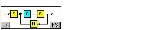
Figure 4-3: The Default Feedback Structure -- Compensator in the Forward Path
In this picture, the lettered boxes represent the following:
The default values for F, H, and C are all 1. Note that this means that by default, the compensator has unity gain. G contains the DC motor model, sys_dc.
Alternative Feedback Structure
Clicking the FS button toggles between the default feedback structure and a feedback structure that places the compensator in the feedback path. This picture shows the alternate feedback stucture.
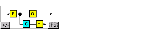
Figure 4-4: Alternate Feedback Structure with the Compensator in the Feedback Loop
| | Importing Models into the SISO Design Tool | Loop Responses | |